
Solar-Powered Environmental Data Logger with Adafruit Feather M0 Express
View and Edit Project In Cirkit Designer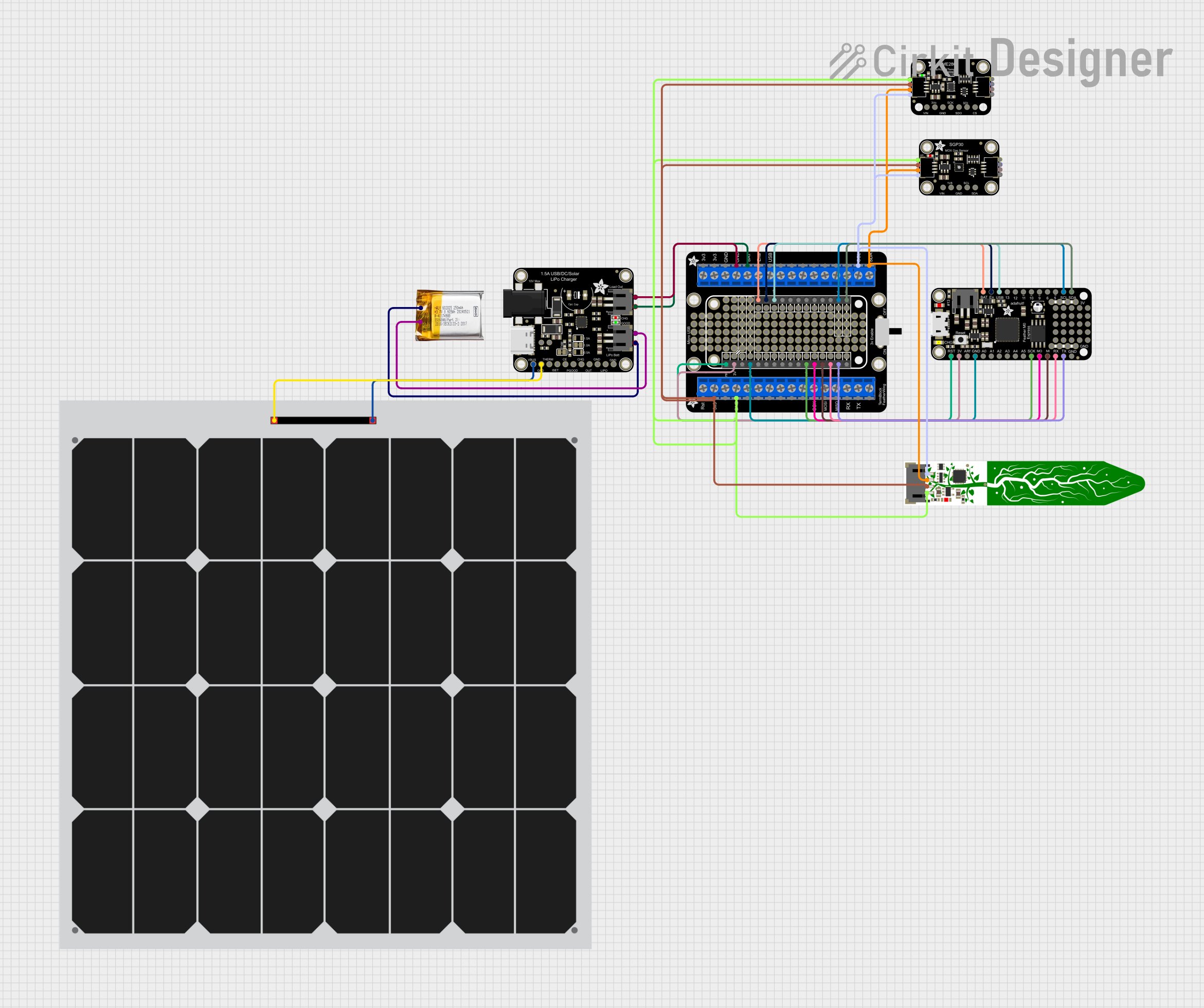
Circuit Documentation
Summary
This circuit is designed to collect environmental data using a set of sensors and log this information for analysis. The core of the circuit is the Adafruit Feather M0 Express microcontroller, which interfaces with a BME280 sensor for atmospheric measurements, an SGP30 sensor for air quality, and a STEMMA Soil Sensor for soil moisture and temperature. The system is powered by a solar panel charging a 3.7v LiPo battery through an Adafruit BQ24074 Solar-DC-USB Lipo Charger. The Adafruit Terminal Breakout FeatherWing is used to facilitate connections to the Feather M0 Express. Communication with the sensors is handled via the I2C protocol.
Component List
Microcontroller
- Adafruit Feather M0 Express: A microcontroller board with built-in USB and battery charging.
Sensors
- Adafruit BME280: A sensor that measures temperature, humidity, and pressure.
- Adafruit SGP30: An air quality sensor that measures eCO2 and TVOC levels.
- Adafruit STEMMA Soil Sensor: A sensor that measures soil moisture and temperature.
Power Management
- Solar Panel: Provides power to charge the battery during daylight.
- 3.7v LiPo Battery: Stores electrical energy for system operation.
- Adafruit BQ24074 Solar-DC-USB Lipo Charger: Manages charging of the LiPo battery from the solar panel or USB.
Interface
- Adafruit Terminal Breakout FeatherWing: Breakout board for easier wiring and prototyping with the Feather M0 Express.
Wiring Details
Adafruit Feather M0 Express
- TX/RX: Serial communication pins.
- MISO/MOSI/SCK: SPI communication pins.
- GND: Ground connection.
- +3V3: 3.3V power supply.
- !RESET: Reset pin.
- VBAT: Battery voltage input.
- EN: Enable pin.
- VBUS: USB power input.
- SCL/SDA: I2C communication pins.
Adafruit Terminal Breakout FeatherWing
- TX/RX: Connected to Feather M0 Express for serial communication.
- MISO/MOSI/SCK: Connected to Feather M0 Express for SPI communication.
- GND: Common ground with Feather M0 Express and all sensors.
- 3V: 3.3V power supply from Feather M0 Express to sensors.
- RESET: Connected to Feather M0 Express reset pin.
- VBAT: Connected to Feather M0 Express for battery voltage monitoring.
- ENABLE: Connected to Feather M0 Express enable pin.
- USB: Connected to Feather M0 Express for USB power input.
- SCL/SDA: I2C communication with all sensors.
Adafruit BME280
- VCC: 3.3V power supply from FeatherWing.
- GND: Ground connection.
- SCK/SCL: I2C clock line.
- SDO/ADR: I2C data line.
Adafruit STEMMA Soil Sensor
- VIN: 3.3V power supply from FeatherWing.
- GND: Ground connection.
- SDA/SCL: I2C communication with FeatherWing.
Solar Panel
- +/-: Connected to the Solar-DC-USB Lipo Charger for charging the battery.
3.7v LiPo Battery
- +Ve/GND: Connected to the Solar-DC-USB Lipo Charger for power storage.
Adafruit SGP30
- VCC: 3.3V power supply from FeatherWing.
- GND: Ground connection.
- SCL/SDA: I2C communication with FeatherWing.
Adafruit BQ24074 Solar-DC-USB Lipo Charger
- D+/D-: USB data lines.
- GND: Ground connection.
- VLIPO: Connected to the LiPo battery.
- OUT: Connected to FeatherWing for battery voltage output.
- !CHG/!PGOOD/!CE: Charge status and control pins.
- ISET: Charge current configuration pin.
- THERM: Battery temperature monitoring pin.
- VBUS: Connected to the Solar Panel for power input.
Documented Code
/*
 * This Arduino Sketch is designed to log data from three sensors: SGP30,
 * STEMMA Soil Sensor, and BME280. The data is read from the sensors,
 * converted to appropriate units, and then logged to the Adafruit Feather
 * M0 Express. The sensors are connected via I2C.
 */

#include <Wire.h>
#include <Adafruit_SGP30.h>
#include <Adafruit_BME280.h>
#include <Adafruit_STEMMA_Soil_Sensor.h>

Adafruit_SGP30 sgp;
Adafruit_BME280 bme;
Adafruit_STEMMA_Soil_Sensor soilSensor;

void setup() {
  Serial.begin(115200);
  while (!Serial) delay(10);

  // Initialize SGP30
  if (!sgp.begin()) {
    Serial.println("SGP30 not found :(");
    while (1);
  }
  Serial.println("SGP30 Found!");

  // Initialize BME280
  if (!bme.begin(0x76)) {
    Serial.println("BME280 not found :(");
    while (1);
  }
  Serial.println("BME280 Found!");

  // Initialize Soil Sensor
  if (!soilSensor.begin()) {
    Serial.println("Soil Sensor not found :(");
    while (1);
  }
  Serial.println("Soil Sensor Found!");
}

void loop() {
  // Read SGP30
  if (!sgp.IAQmeasure()) {
    Serial.println("SGP30 measurement failed");
    return;
  }
  Serial.print("eCO2: "); Serial.print(sgp.eCO2); Serial.print(" ppm, TVOC: ");
  Serial.print(sgp.TVOC); Serial.println(" ppb");

  // Read BME280
  Serial.print("Temperature: "); Serial.print(bme.readTemperature());
  Serial.print(" °C, Humidity: "); Serial.print(bme.readHumidity());
  Serial.print(" %, Pressure: "); Serial.print(bme.readPressure() / 100.0F);
  Serial.println(" hPa");

  // Read Soil Sensor
  Serial.print("Soil Moisture: "); Serial.print(soilSensor.readMoisture());
  Serial.print(" %, Soil Temperature: "); Serial.print(soilSensor.readTemperature());
  Serial.println(" °C");

  delay(2000); // Delay between readings
}
This code initializes the sensors and reads their data in a loop, printing the results to the serial monitor. The delay between readings is set to 2 seconds.