Cirkit Designer
Your all-in-one circuit design IDE
Home /
Project Documentation
Arduino Mega 2560-Based Smart Water Pump System with Bluetooth Control
Circuit Documentation
Summary
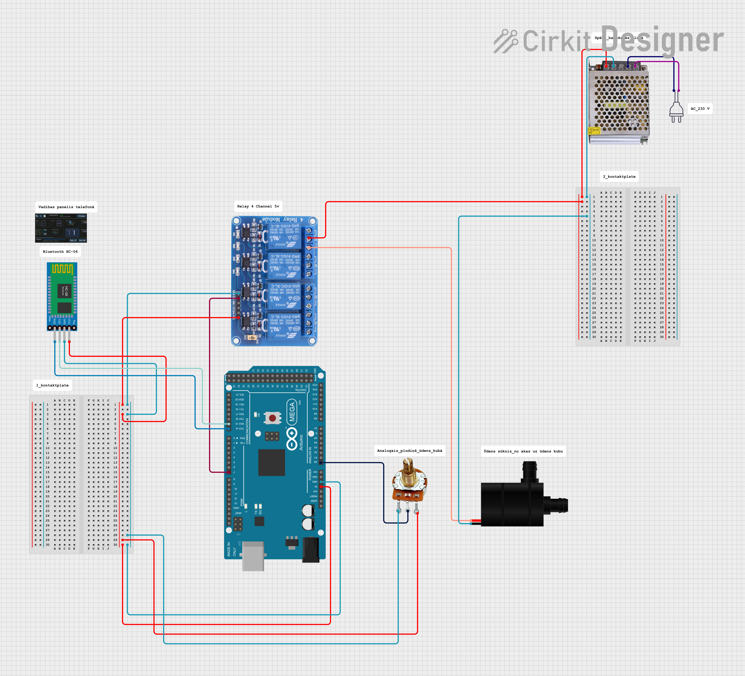
This circuit involves an Arduino Mega 2560 microcontroller, a 4-channel relay module, a 12V power supply, a Bluetooth module (HC-06), a rotary potentiometer, and a water pump. The Arduino Mega 2560 controls the relay module, which in turn controls the water pump. The Bluetooth module allows for wireless communication, and the potentiometer provides an analog input to the Arduino.
Component List
Arduino Mega 2560
- Description: A microcontroller board based on the ATmega2560.
- Pins: IOREF, RESET, 3V3, 5V, GND, VIN, A0-A15, D0-D53, AREF, SDA, SCL
Relay 4 Channel 5v
- Description: A relay module that allows control of high voltage devices with a low voltage signal.
- Pins: GND, IN1, IN2, IN3, IN4, VCC, COM1, COM2, COM3, COM4, NO1, NO2, NO3, NO4, NC1, NC2, NC3, NC4
POWER SUPPLY 12V 5AMP
- Description: A power supply that converts 220V AC to 12V DC.
- Pins: 220V Positive Pole (AC), 220V Negative Pole (AC), GND, GND (DC), 12V-24V Output (DC)
Power 220v
- Description: A standard 220V AC power source.
- Pins: hot wire, neutral wire
PR-Rotary Potentiometer
- Description: A variable resistor used to provide an adjustable voltage.
- Pins: GND, OUT, VCC
Water Pump
- Description: A pump that operates on DC voltage.
- Pins: VCC, GND
Bluetooth HC-06
- Description: A Bluetooth module for wireless communication.
- Pins: VCC, GND, TXD, RXD
Wiring Details
Arduino Mega 2560
- 5V: Connected to VCC of Relay 4 Channel 5v, Bluetooth HC-06, and PR-Rotary Potentiometer.
- GND: Connected to GND of Relay 4 Channel 5v, Bluetooth HC-06, and PR-Rotary Potentiometer.
- A0: Connected to OUT of PR-Rotary Potentiometer.
- D15/RX3: Connected to TXD of Bluetooth HC-06.
- D14/TX3: Connected to RXD of Bluetooth HC-06.
- D7 PWM: Connected to IN1 of Relay 4 Channel 5v.
Relay 4 Channel 5v
- VCC: Connected to 5V of Arduino Mega 2560.
- GND: Connected to GND of Arduino Mega 2560.
- IN1: Connected to D7 PWM of Arduino Mega 2560.
- COM1: Connected to 12V-24V Output (DC) of POWER SUPPLY 12V 5AMP.
- NO1: Connected to VCC of Water Pump.
POWER SUPPLY 12V 5AMP
- 12V-24V Output (DC): Connected to COM1 of Relay 4 Channel 5v.
- GND (DC): Connected to GND of Water Pump.
- 220V Positive Pole (AC): Connected to hot wire of Power 220v.
- 220V Negative Pole (AC): Connected to neutral wire of Power 220v.
Power 220v
- hot wire: Connected to 220V Positive Pole (AC) of POWER SUPPLY 12V 5AMP.
- neutral wire: Connected to 220V Negative Pole (AC) of POWER SUPPLY 12V 5AMP.
PR-Rotary Potentiometer
- VCC: Connected to 5V of Arduino Mega 2560.
- GND: Connected to GND of Arduino Mega 2560.
- OUT: Connected to A0 of Arduino Mega 2560.
Water Pump
- VCC: Connected to NO1 of Relay 4 Channel 5v.
- GND: Connected to GND (DC) of POWER SUPPLY 12V 5AMP.
Bluetooth HC-06
- VCC: Connected to 5V of Arduino Mega 2560.
- GND: Connected to GND of Arduino Mega 2560.
- TXD: Connected to D15/RX3 of Arduino Mega 2560.
- RXD: Connected to D14/TX3 of Arduino Mega 2560.
Documented Code
Arduino Mega 2560 Code (sketch.ino)
void setup() {
  // put your setup code here, to run once:

}

void loop() {
  // put your main code here, to run repeatedly:

}
Additional Documentation (documentation.txt)