
Arduino-Controlled Robotics Platform with Ultrasonic Sensing and Dual Motor Drivers
View and Edit Project In Cirkit Designer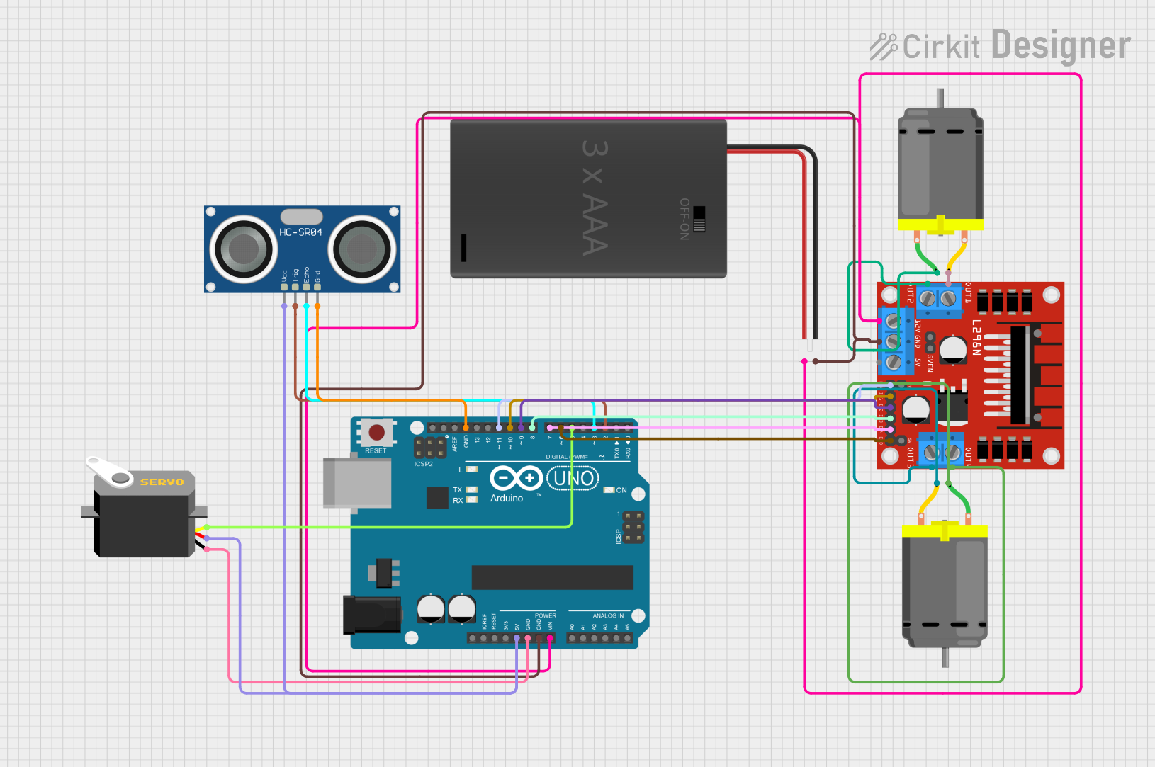
Circuit Documentation
Summary of the Circuit
This circuit is designed to control a servo motor and two DC motors using an Arduino UNO microcontroller. It also includes an HC-SR04 ultrasonic sensor for distance measurement. The Arduino UNO is powered by a 3xAAA battery pack and interfaces with an L298N DC motor driver to control the motors. The servo motor is directly connected to the Arduino for control signals and power. The ultrasonic sensor is used for input and is connected to the Arduino's digital pins.
Component List
Arduino UNO
- Microcontroller board based on the ATmega328P
- It has 14 digital input/output pins, 6 analog inputs, a 16 MHz quartz crystal, a USB connection, a power jack, an ICSP header, and a reset button.
DC Motor (x2)
- A simple electric motor that runs on direct current (DC) electricity.
- It has two pins for power connection.
Servo
- A rotary actuator or linear actuator that allows for precise control of angular or linear position, velocity, and acceleration.
- It has three pins: power (VCC), ground (GND), and control signal (pulse).
L298N DC Motor Driver
- A high-power motor driver capable of driving up to two DC motors.
- It has several pins for motor outputs, power supply, and control inputs.
HC-SR04 Ultrasonic Sensor
- An ultrasonic distance sensor that can measure distances from 2cm to 400cm with an accuracy of 3mm.
- It has four pins: VCC, TRIG, ECHO, and GND.
3xAAA Battery Pack with Switch and JST
- A battery pack that holds three AAA batteries and includes a switch and a JST connector for power supply.
- It has two pins: positive (POS) and negative (NEG).
Wiring Details
Arduino UNO
- 5V: Connected to the Servo VCC and HC-SR04 VCC.
- GND: Common ground with Servo, HC-SR04, L298N, and Battery Pack NEG.
- Vin: Connected to the Battery Pack POS and L298N 12V.
- D11: Connected to L298N ENA.
- D10: Connected to L298N IN1.
- D9: Connected to L298N IN2.
- D8: Connected to L298N IN3.
- D7: Connected to L298N IN4.
- D6: Connected to L298N ENB.
- D5: Connected to Servo pulse.
- D3: Connected to HC-SR04 ECHO.
- D2: Connected to HC-SR04 TRIG.
DC Motor #1
- Pin 1: Connected to L298N OUT2.
- Pin 2: Connected to L298N OUT1.
DC Motor #2
- Pin 1: Connected to L298N OUT4.
- Pin 2: Connected to L298N OUT3.
Servo
- VCC: Connected to Arduino 5V.
- GND: Connected to Arduino GND.
- Pulse: Connected to Arduino D5.
L298N DC Motor Driver
- OUT1, OUT2: Connected to DC Motor #1.
- OUT3, OUT4: Connected to DC Motor #2.
- 12V: Connected to Battery Pack POS.
- GND: Common ground with Arduino and Battery Pack NEG.
- ENA, IN1, IN2, IN3, IN4, ENB: Controlled by Arduino digital pins D11, D10, D9, D8, D7, D6 respectively.
HC-SR04 Ultrasonic Sensor
- VCC: Connected to Arduino 5V.
- TRIG: Connected to Arduino D2.
- ECHO: Connected to Arduino D3.
- GND: Connected to Arduino GND.
3xAAA Battery Pack with Switch and JST
- POS: Connected to Arduino Vin and L298N 12V.
- NEG: Common ground with Arduino and L298N.
Documented Code
/*
 * This Arduino sketch controls a green LED using two push buttons.
 * When P/B 1 is pressed, the green LED turns on.
 * When P/B 2 is pressed, the green LED turns off.
 */

const int buttonPin1 = 2; // P/B 1 connected to digital pin 2
const int buttonPin2 = 3; // P/B 2 connected to digital pin 3
const int ledPin = 13;    // Green LED connected to digital pin 13

void setup() {
  pinMode(buttonPin1, INPUT); // Set button pin 1 as input
  pinMode(buttonPin2, INPUT); // Set button pin 2 as input
  pinMode(ledPin, OUTPUT);    // Set LED pin as output
}

void loop() {
  if (digitalRead(buttonPin1) == HIGH) {
    digitalWrite(ledPin, HIGH); // Turn on LED
  }
  if (digitalRead(buttonPin2) == HIGH) {
    digitalWrite(ledPin, LOW);  // Turn off LED
  }
}
Note: The provided code does not match the described functionality of the circuit. The code is for controlling an LED with push buttons, while the circuit is designed to control motors and read from an ultrasonic sensor. The code needs to be updated to reflect the actual components and functionality of the circuit.