ESP8266 NodeMCU Controlled Smart Light with Gesture Sensing and Relay Switching
Circuit Documentation
Summary of the Circuit
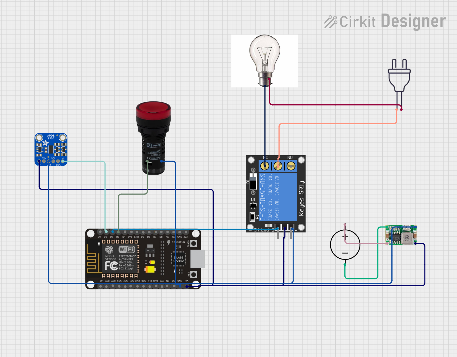
This circuit is designed to interface an ESP8266 NodeMCU microcontroller with various components including an Adafruit APDS-9960 sensor, a 1-Channel Relay, a 9W-10W Bulb, a Pilot Lamp, a Mini 360 Buck Converter, and a DC Power Source. The circuit is likely intended for some form of automation or control system, where the ESP8266 NodeMCU acts as the central processing unit, the APDS-9960 sensor provides input signals, the relay controls power to the bulb, and the pilot lamp indicates the system status. The Mini 360 Buck Converter is used to step down the voltage from the DC Power Source to a level suitable for the microcontroller and other components.
Component List
ESP8266 NodeMCU
- Microcontroller with WiFi capability
- Pins: D0, D1, D2, D3, D4, 3V3, GND, D5, D6, D7, D8, RX, TX, A0, RSV, SD3, SD2, SD1, CMD, SD0, CLK, EN, RST, VIN
Adafruit APDS-9960
- Proximity, light, RGB, and gesture sensor
- Pins: VIN, 3.3V, GND, SCL, SDA, INT
1-Channel Relay (5V 10A)
- Electromechanical switch used for controlling high power devices
- Pins: NC, signal, C, power, NO, ground
Power 220V
- Mains power supply
- Pins: hot wire, neutral wire
9W-10W Bulb
- Light-emitting component
- Pins: +VE, -VE
Pilot Lamp Red
- Indicator lamp
- Pins: X1, X2
Mini 360 Buck Converter
- Voltage step-down (buck) converter
- Pins: IN-, OUT-, OUT+, IN+
DC Power Source
- External power supply for the circuit
- Pins: Ground, Positive
Wiring Details
ESP8266 NodeMCU
- D1 connected to Adafruit APDS-9960 INT
- D2 connected to 1-Channel Relay signal
- D3 connected to Pilot Lamp Red X1
- GND connected to 1-Channel Relay ground, Adafruit APDS-9960 GND, Pilot Lamp Red X2, Mini 360 Buck Converter OUT-
- VIN connected to 1-Channel Relay power, Adafruit APDS-9960 VIN, Mini 360 Buck Converter OUT+
Adafruit APDS-9960
- INT connected to ESP8266 NodeMCU D1
- GND connected to ESP8266 NodeMCU GND, 1-Channel Relay ground, Pilot Lamp Red X2, Mini 360 Buck Converter OUT-
- VIN connected to ESP8266 NodeMCU VIN, 1-Channel Relay power, Mini 360 Buck Converter OUT+
1-Channel Relay (5V 10A)
- signal connected to ESP8266 NodeMCU D2
- ground connected to ESP8266 NodeMCU GND, Adafruit APDS-9960 GND, Pilot Lamp Red X2, Mini 360 Buck Converter OUT-
- power connected to ESP8266 NodeMCU VIN, Adafruit APDS-9960 VIN, Mini 360 Buck Converter OUT+
- NC connected to 9W-10W Bulb +VE
- C connected to Power 220V hot wire
Power 220V
- hot wire connected to 1-Channel Relay C
- neutral wire connected to 9W-10W Bulb -VE
9W-10W Bulb
- +VE connected to 1-Channel Relay NC
- -VE connected to Power 220V neutral wire
Pilot Lamp Red
- X1 connected to ESP8266 NodeMCU D3
- X2 connected to ESP8266 NodeMCU GND, 1-Channel Relay ground, Adafruit APDS-9960 GND, Mini 360 Buck Converter OUT-
Mini 360 Buck Converter
- IN- connected to DC Power Source Ground
- OUT- connected to ESP8266 NodeMCU GND, 1-Channel Relay ground, Adafruit APDS-9960 GND, Pilot Lamp Red X2
- OUT+ connected to ESP8266 NodeMCU VIN, 1-Channel Relay power, Adafruit APDS-9960 VIN
- IN+ connected to DC Power Source Positive
DC Power Source
- Ground connected to Mini 360 Buck Converter IN-
- Positive connected to Mini 360 Buck Converter IN+
Documented Code
No code has been provided for the microcontroller(s) in this circuit. If code is later provided, it should be documented here with explanations of how the code interacts with the hardware components and implements the desired functionality of the circuit.