Cirkit Designer
Your all-in-one circuit design IDE
Home /
Project Documentation
Arduino-Powered Wireless Relay Control with ADXL335 Accelerometer Feedback

Circuit Documentation
Summary
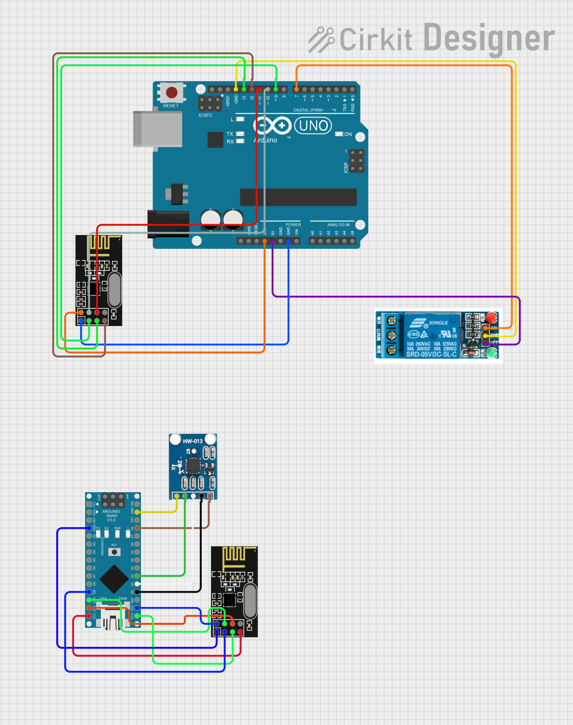
The circuit in question is composed of an Arduino UNO, an Arduino Nano, two NRF24L01 wireless transceiver modules, a 5V relay, and an AITrip ADXL335 GY-61 accelerometer module. The Arduino UNO and Nano serve as the main microcontrollers for processing and controlling the various peripherals. The NRF24L01 modules enable wireless communication, while the 5V relay allows for controlling higher power loads. The ADXL335 module is used for sensing acceleration in three axes.
Component List
Arduino UNO
- Microcontroller board based on the ATmega328P
- It has 14 digital input/output pins, 6 analog inputs, a 16 MHz quartz crystal, a USB connection, a power jack, an ICSP header, and a reset button.
Arduino Nano
- Compact microcontroller board based on the ATmega328P
- Similar to the Arduino UNO but in a smaller form factor, it offers 14 digital input/output pins, 8 analog inputs, and a mini-USB port.
NRF24L01 Wireless Transceiver Module (x2)
- 2.4GHz wireless transceiver module
- Features include up to 2Mbps data rate, 125 channels, and low power consumption.
5V Relay
- Electromechanical switch with a coil rated at 5V
- Provides a Normally Open (NO), a Normally Closed (NC), and a Common terminal (COM) for switching applications.
AITrip ADXL335 GY-61 Accelerometer Module
- Analog three-axis accelerometer
- Provides analog voltage outputs for the X, Y, and Z axes.
Wiring Details
Arduino UNO
3.3Vconnected to NRF24L01 VCC (3V)5Vconnected to 5V relay VCCGNDconnected to NRF24L01 GND and 5V relay GNDD13connected to NRF24L01 SCKD12connected to NRF24L01 MISOD11connected to NRF24L01 MOSID10connected to NRF24L01 CSND9connected to NRF24L01 CED7connected to 5V relay In
Arduino Nano
GNDconnected to NRF24L01 GND and ADXL335 GND5Vconnected to ADXL335 VCC3V3connected to NRF24L01 VCC (3V)D13/SCKconnected to NRF24L01 SCKD12/MISOconnected to NRF24L01 MISOD11/MOSIconnected to NRF24L01 MOSID10connected to NRF24L01 CSND9connected to NRF24L01 CEA2connected to ADXL335 Z-OutA1connected to ADXL335 Y-OutA0connected to ADXL335 X-Out
NRF24L01 Wireless Transceiver Module
- Two instances, each connected to a corresponding Arduino (UNO/Nano) as detailed above.
5V Relay
VCCconnected to Arduino UNO 5VGNDconnected to Arduino UNO GNDInconnected to Arduino UNO D7
AITrip ADXL335 GY-61 Accelerometer Module
VCCconnected to Arduino Nano 5VGNDconnected to Arduino Nano GNDZ-Outconnected to Arduino Nano A2Y-Outconnected to Arduino Nano A1X-Outconnected to Arduino Nano A0
Documented Code
Arduino UNO Code
void setup() {
  // put your setup code here, to run once:

}

void loop() {
  // put your main code here, to run repeatedly:

}
Filename: sketch.ino
Arduino Nano Code
void setup() {
  // put your setup code here, to run once:

}

void loop() {
  // put your main code here, to run repeatedly:

}
Filename: sketch.ino
Note: The provided code for both the Arduino UNO and Nano is a template with empty setup and loop functions. This code will need to be filled in with the specific logic required for the circuit's intended operation.