Arduino and ESP32-CAM Controlled Dual DC Motor System with IR Sensors and Wi-Fi Connectivity
Circuit Documentation
Summary
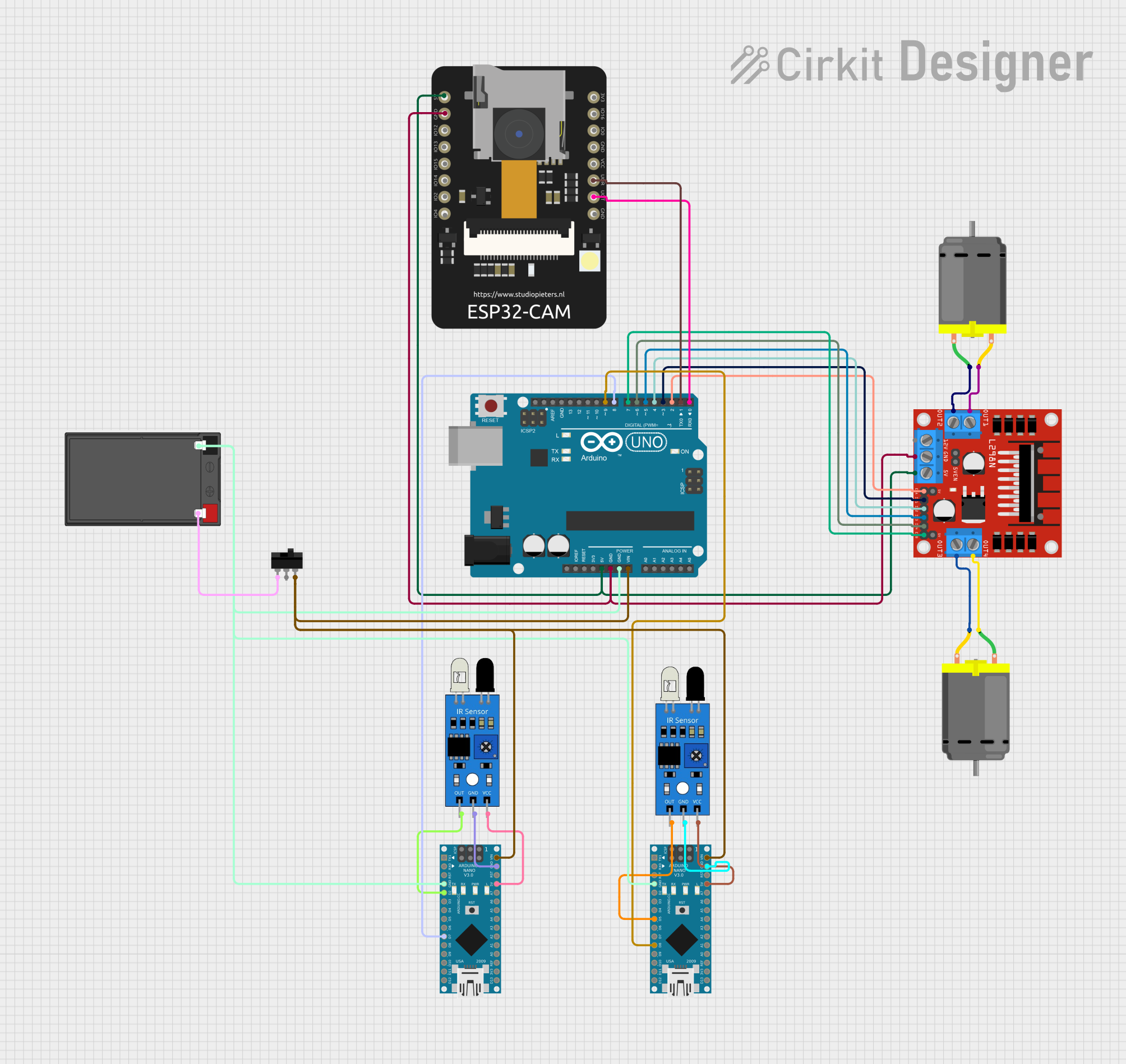
This circuit integrates multiple microcontrollers, sensors, a motor driver, DC motors, a camera module, a power source, and a toggle switch. The primary microcontroller is an Arduino UNO, which interfaces with an ESP32 CAM module, two Arduino Nanos, two IR sensors, an L298N DC motor driver, and two DC motors. The circuit is powered by a battery connected through a toggle switch, providing a means to control the power flow. The Arduino UNO and Nanos are responsible for processing signals from the IR sensors and controlling the DC motors via the motor driver. The ESP32 CAM module is connected for potential image capture or video streaming applications.
Component List
- Arduino UNO: A microcontroller board based on the ATmega328P, featuring digital and analog I/O pins.
- Arduino Nano (x2): Compact microcontroller boards based on the ATmega328, similar to the UNO but in a smaller form factor.
- IR Sensor (x2): Infrared sensors used for detecting proximity or measuring distance.
- L298N DC Motor Driver: A module capable of driving two DC motors with direction and speed control.
- DC Motor (x2): Electric motors that convert electrical energy into mechanical rotation.
- ESP32 CAM: A small camera module with Wi-Fi capabilities, based on the ESP32 chip.
- Battery: The power source for the circuit.
- Toggle Switch: A switch to control the power supply to the circuit.
Wiring Details
Arduino UNO
- 5V: Connected to the 5V of the L298N motor driver and ESP32 CAM.
- GND: Common ground with L298N motor driver, ESP32 CAM, and battery.
- Vin: Connected to the VIN of both Arduino Nanos through a toggle switch.
- D0-D9: Digital pins connected to various components for control signals.
Arduino Nano (x2)
- 5V: Powers the IR sensors.
- GND: Common ground with the IR sensors and battery.
- VIN: Powered from the battery through a toggle switch.
- D2, D5, D7, D8: Digital pins used for interfacing with the IR sensors and Arduino UNO.
IR Sensor (x2)
- VCC: Powered by the 5V pin of the corresponding Arduino Nano.
- GND: Common ground with the corresponding Arduino Nano.
- Out: Output signal connected to a digital pin on the corresponding Arduino Nano.
L298N DC Motor Driver
- 5V: Receives power from the Arduino UNO 5V pin.
- GND: Common ground with Arduino UNO and battery.
- ENA, ENB, IN1-IN4: Control signals from Arduino UNO for motor operation.
- OUT1-OUT4: Connected to the DC motors for driving them.
DC Motor (x2)
- Pin 1 & Pin 2: Connected to the OUT1-OUT4 of the L298N motor driver to receive drive signals.
ESP32 CAM
- 5V: Powered by the 5V pin of the Arduino UNO.
- GND: Common ground with Arduino UNO.
- GPIO3 / RX, GPIO1 / TX: Serial communication with the Arduino UNO.
Battery
- +: Connected to the toggle switch.
- -: Common ground with the circuit.
Toggle Switch
- L1: Connected to the positive terminal of the battery.
- COM: Connected to the VIN of the Arduino UNO and Nanos to control power.
Documented Code
Arduino UNO Code
void setup() {
  // put your setup code here, to run once:

}

void loop() {
  // put your main code here, to run repeatedly:

}
Arduino Nano Code (Instance 1)
void setup() {
  // put your setup code here, to run once:

}

void loop() {
  // put your main code here, to run repeatedly:

}
Arduino Nano Code (Instance 2)
void setup() {
  // put your setup code here, to run once:

}

void loop() {
  // put your main code here, to run repeatedly:

}
Note: The provided code for each microcontroller is a template and does not contain specific functionality. It is expected that the user will add the necessary code to interact with the connected components and perform the desired operations.