
Arduino UNO and MCP4725 DAC Module for Digital-to-Analog Conversion
View and Edit Project In Cirkit Designer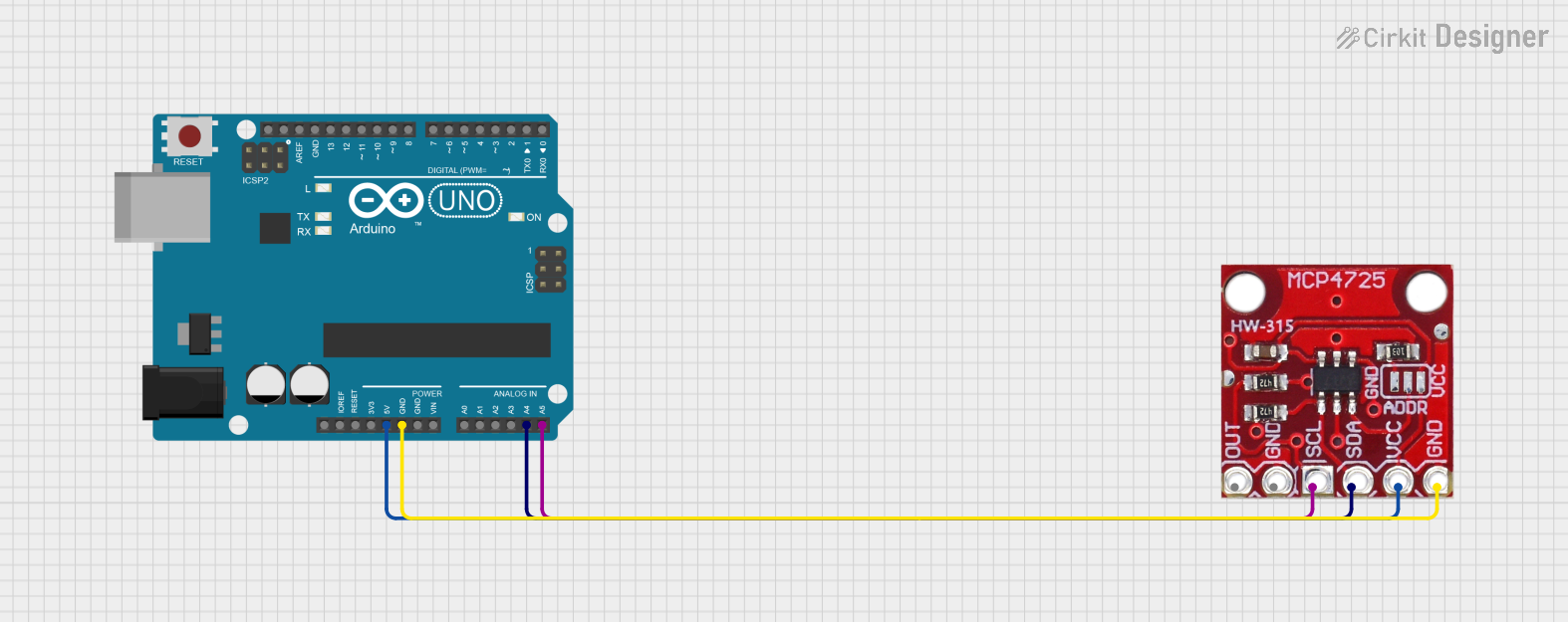
Circuit Documentation
Summary
This circuit involves an Arduino UNO microcontroller connected to an xcluma MCP4725 I2C DAC Breakout module. The Arduino UNO provides power and I2C communication to the DAC module, which can be used for digital-to-analog conversion.
Component List
Arduino UNO
- Description: A microcontroller board based on the ATmega328P.
- Pins: UNUSED, IOREF, Reset, 3.3V, 5V, GND, Vin, A0, A1, A2, A3, A4, A5, SCL, SDA, AREF, D13, D12, D11, D10, D9, D8, D7, D6, D5, D4, D3, D2, D1, D0
- Purpose in Circuit: Acts as the main controller, providing power and I2C communication to the DAC module.
xcluma MCP4725 I2C DAC Breakout module
- Description: A digital-to-analog converter module that communicates via I2C.
- Pins: SDA, VCC, OUT, GND, SCL
- Purpose in Circuit: Converts digital signals from the Arduino into analog signals.
Wiring Details
Arduino UNO
- 5V: Connected to VCC of the xcluma MCP4725 I2C DAC Breakout module.
- GND: Connected to GND of the xcluma MCP4725 I2C DAC Breakout module.
- A4: Connected to SDA of the xcluma MCP4725 I2C DAC Breakout module.
- A5: Connected to SCL of the xcluma MCP4725 I2C DAC Breakout module.
xcluma MCP4725 I2C DAC Breakout module
- VCC: Connected to 5V of the Arduino UNO.
- GND: Connected to GND of the Arduino UNO.
- SDA: Connected to A4 of the Arduino UNO.
- SCL: Connected to A5 of the Arduino UNO.
Code Documentation
Arduino UNO Code
void setup() {
  // put your setup code here, to run once:

}

void loop() {
  // put your main code here, to run repeatedly:

}
This code is a basic template for the Arduino UNO. The setup() function is where you initialize settings, and the loop() function is where the main code runs repeatedly.
Additional Documentation
This section is reserved for any additional documentation or notes related to the code or circuit.