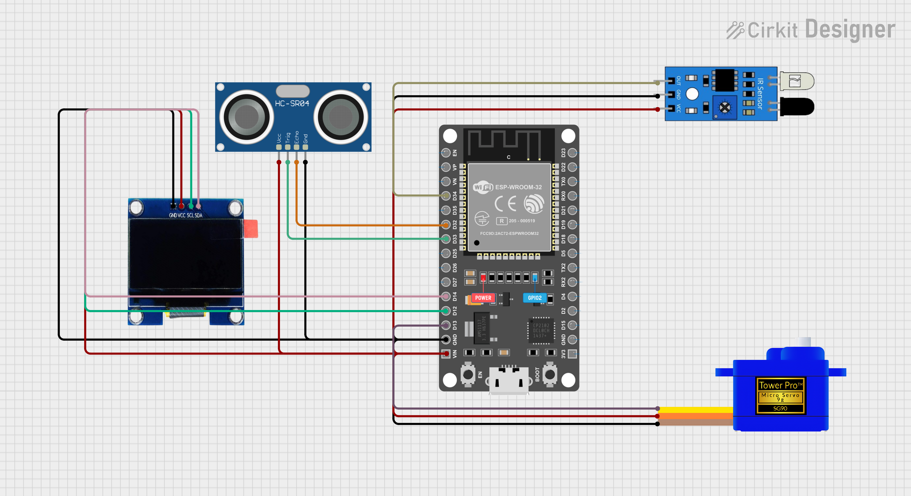
ESP32-Based Obstacle Detection System with Ultrasonic Sensor and IR Sensor

Circuit Documentation
Summary of the Circuit
This circuit integrates various components with an ESP32 microcontroller to create a system capable of interfacing with sensors, an OLED display, and a servomotor. The ESP32 serves as the central processing unit, managing inputs from an IR sensor and an HC-SR04 ultrasonic sensor, and controlling the output to an OLED display and a Servomotor SG90. The circuit is designed for applications that require distance measurement, motion detection, and visual feedback.
Component List
ESP 32 DEVKIT V1 (30 pins)
- Description: A microcontroller board based on the ESP32 chip, featuring Wi-Fi and Bluetooth connectivity, with a wide range of GPIO pins for interfacing with various peripherals.
- Purpose: Acts as the central controller for the circuit, processing sensor data and controlling the display and servomotor.
HC-SR04 Ultrasonic Sensor
- Description: A distance measuring sensor that uses ultrasonic sound waves to determine the distance to an object.
- Purpose: Provides distance measurements to the ESP32 for processing.
IR Sensor
- Description: An infrared sensor capable of detecting infrared light, often used for proximity or motion detection.
- Purpose: Serves as a motion or proximity detector in the circuit.
Servomotor SG90
- Description: A small and lightweight servomotor commonly used for precise angular movement or positioning.
- Purpose: Receives commands from the ESP32 to adjust its position based on sensor inputs.
OLED 1.3"
- Description: A small OLED display capable of showing text and graphics in monochrome.
- Purpose: Displays information or readings from the sensors, as controlled by the ESP32.
Wiring Details
ESP 32 DEVKIT V1 (30 pins)
- D34: Connected to the IR sensor output.
- D32: Connected to the ECHO pin of the HC-SR04 Ultrasonic Sensor.
- D33: Connected to the TRIG pin of the HC-SR04 Ultrasonic Sensor.
- D14: Connected to the SDA pin of the OLED 1.3" display.
- D12: Connected to the SCL pin of the OLED 1.3" display.
- D13: Connected to the SIG pin of the Servomotor SG90.
- GND: Common ground connected to the GND pins of all other components.
- VIN: Power input connected to the VCC pins of all other components.
HC-SR04 Ultrasonic Sensor
- VCC: Connected to the VIN pin of the ESP32.
- TRIG: Connected to the D33 pin of the ESP32.
- ECHO: Connected to the D32 pin of the ESP32.
- GND: Connected to the common ground.
IR Sensor
- Out: Connected to the D34 pin of the ESP32.
- GND: Connected to the common ground.
- VCC: Connected to the VIN pin of the ESP32.
Servomotor SG90
- SIG: Connected to the D13 pin of the ESP32.
- VCC: Connected to the VIN pin of the ESP32.
- GND: Connected to the common ground.
OLED 1.3"
- GND: Connected to the common ground.
- VCC: Connected to the VIN pin of the ESP32.
- SCL: Connected to the D12 pin of the ESP32.
- SDA: Connected to the D14 pin of the ESP32.
Documented Code
No code has been provided for the microcontroller. The documentation of the code would typically include setup routines, main program logic, function definitions, and comments explaining the purpose and functionality of each section of the code. Since no code is available, this section cannot be completed.