
Wi-Fi Enabled Environmental Monitoring Station with Interactive Indicators
View and Edit Project In Cirkit Designer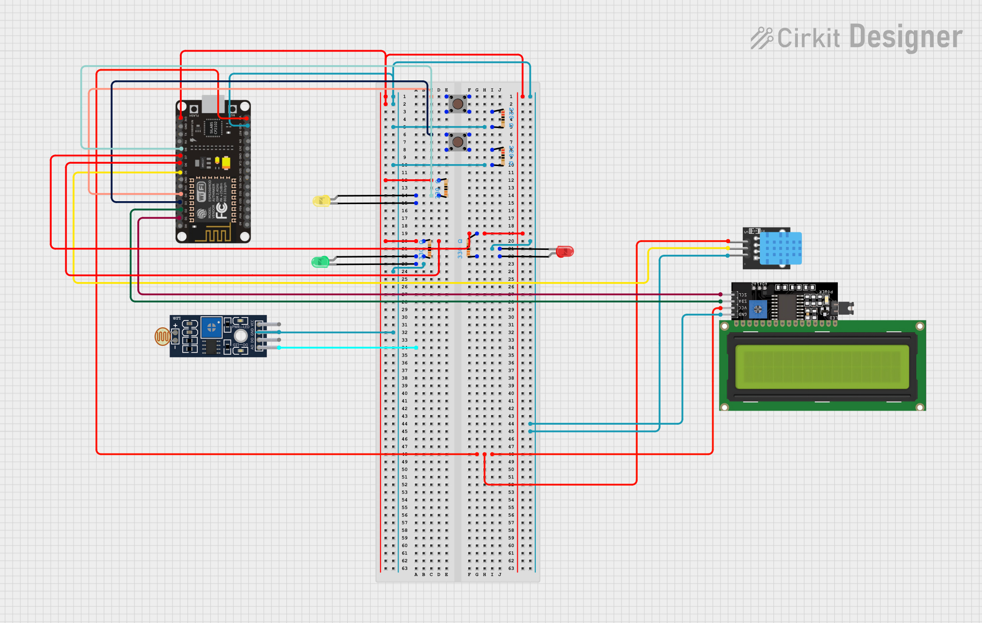
Circuit Documentation
Summary
The circuit in question appears to be a multifunctional device incorporating various sensors, user input interfaces, and output devices, all controlled by an ESP8266 NodeMCU microcontroller. The circuit includes LEDs for visual feedback, pushbuttons for user input, an LDR sensor for light detection, a DHT11 sensor for temperature and humidity measurement, and an LCD display for data output. The circuit is designed to interact with the physical environment and provide a user interface.
Component List
LEDs
- Red LED: A two-pin light-emitting diode that emits red light.
- Yellow LED: A two-pin light-emitting diode that emits yellow light.
- Green LED: A two-pin light-emitting diode that emits green light.
Sensors
- Sensor LDR LM393: A light-dependent resistor sensor module that detects the intensity of light.
- KY-015 DHT11: A sensor module for measuring temperature and humidity.
User Input
- Pushbutton: A standard pushbutton used for user input.
Display
- LCD Display 16x4 I2C: A 16x4 character LCD display module with an I2C interface for displaying data.
Microcontroller
- ESP8266 NodeMCU: A microcontroller with Wi-Fi capabilities, equipped with multiple digital and analog pins for interfacing with various components.
Resistors
- 330 Ohm Resistors: Used for current limiting, typically for LEDs.
- 220 Ohm Resistors: Also used for current limiting or as pull-up/pull-down resistors.
Wiring Details
Red LED
- Cathode: Connected to the ground (GND) through a 330 Ohm resistor.
- Anode: Connected to a digital pin on the ESP8266 NodeMCU for control.
Yellow LED
- Cathode: Connected to the ground (GND) through a 330 Ohm resistor.
- Anode: Connected to a digital pin on the ESP8266 NodeMCU for control.
Green LED
- Cathode: Connected to the ground (GND) through a 330 Ohm resistor.
- Anode: Connected to a digital pin on the ESP8266 NodeMCU for control.
Sensor LDR LM393
- A0: Analog output, not connected in the provided net list.
- D0: Digital output, not connected in the provided net list.
- GND: Connected to the ground (GND).
- VCC: Not connected in the provided net list.
KY-015 DHT11
- 5V: Connected to the VIN pin on the ESP8266 NodeMCU.
- S: Connected to a digital pin on the ESP8266 NodeMCU for data reading.
- GND: Connected to the ground (GND).
Pushbuttons
- Pin 3 (out): Connected to digital pins on the ESP8266 NodeMCU for detecting button presses.
- Pin 4 (out): Not connected in the provided net list.
- Pin 1 (in): Not connected in the provided net list.
- Pin 2 (in): Connected to the ground (GND) through a 220 Ohm resistor.
LCD Display 16x4 I2C
- SCL: Connected to the D1 pin on the ESP8266 NodeMCU for I2C clock.
- SDA: Connected to the D2 pin on the ESP8266 NodeMCU for I2C data.
- VCC: Connected to the VIN pin on the ESP8266 NodeMCU.
- GND: Connected to the ground (GND).
Resistors
- 330 Ohm Resistors: Connected between the cathodes of the LEDs and the ground (GND).
- 220 Ohm Resistors: Connected between the ground (GND) and the input pins of the pushbuttons.
ESP8266 NodeMCU
- Digital Pins (D3, D4, D5, D6, D7, D8): Connected to various components for control and data reading.
- 3V3: Connected to a 330 Ohm resistor.
- GND: Common ground for various components.
- VIN: Power supply for the circuit, connected to the VCC pins of the LCD and DHT11 sensor.
Documented Code
No code was provided in the input. The ESP8266 NodeMCU would typically be programmed to control the LEDs, read sensor data, respond to pushbutton inputs, and display information on the LCD. The code would be written in a language compatible with the ESP8266, such as Lua or C/C++ using the Arduino IDE. It would include libraries for handling I2C communication with the LCD and reading data from the DHT11 sensor.