
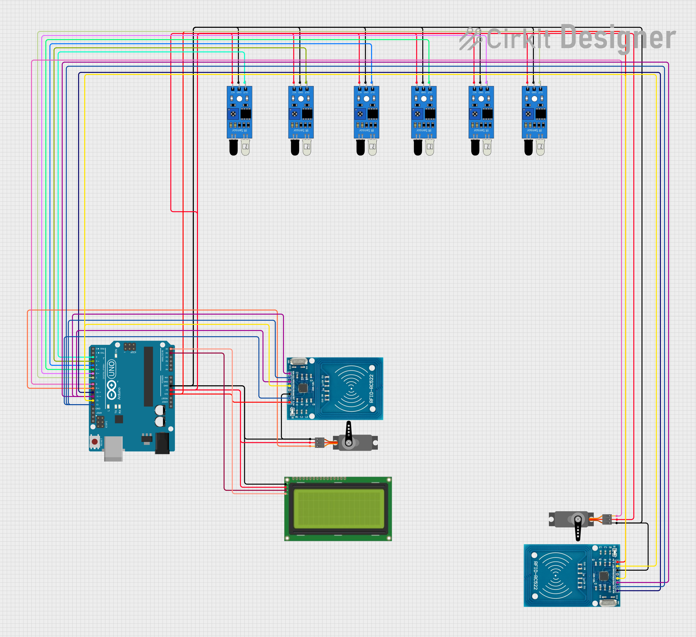
Circuit Documentation
Summary
The circuit in question is designed to interface multiple sensors, actuators, and communication modules with an Arduino UNO microcontroller. The circuit includes IR sensors for detecting objects or movements, RFID-RC522 modules for RFID communication, servo motors for actuation, and an LCD (20x4 with I2C interface) for displaying information. The Arduino UNO serves as the central processing unit, controlling the sensors, actuators, and communication with the LCD.
Component List
IR Sensors
- Description: Infrared sensors used for object detection or motion sensing.
- Pins:
out,gnd,vcc
RFID-RC522
- Description: RFID reader/writer module for contactless communication using radio frequency.
- Pins:
VCC (3.3V),RST,GND,IRQ,MISO,MOSI,SCK,SDA
Servo Motors
- Description: Actuators capable of precise position control.
- Pins:
GND,VCC,PWM
LCD 20x4 I2C
- Description: A 20x4 character LCD display with an I2C interface for displaying data.
- Pins:
GND,5v,SCA,SCL
Arduino UNO
- Description: A microcontroller board based on the ATmega328P.
- Pins:
UNUSED,IOREF,Reset,3.3V,5V,GND,Vin,A0toA5,SCL,SDA,AREF,D13toD0
Wiring Details
IR Sensors
- VCC: Connected to Arduino UNO 5V.
- GND: Connected to Arduino UNO GND.
- OUT: Connected to individual digital pins on the Arduino UNO (D2 to D7).
RFID-RC522
- VCC (3.3V): Connected to Arduino UNO 3.3V.
- RST: Connected to Arduino UNO D13.
- GND: Connected to Arduino UNO GND.
- IRQ: Not connected.
- MISO: Connected to Arduino UNO D12.
- MOSI: Connected to Arduino UNO D11.
- SCK: Connected to Arduino UNO D13.
- SDA: Connected to Arduino UNO D10.
Servo Motors
- VCC: Connected to Arduino UNO 5V.
- GND: Connected to Arduino UNO GND.
- PWM: Connected to Arduino UNO D8 and D9 for the two servos.
LCD 20x4 I2C
- GND: Connected to Arduino UNO GND.
- 5v: Connected to Arduino UNO 5V.
- SCA: Connected to Arduino UNO A4.
- SCL: Connected to Arduino UNO A5.
Documented Code
void setup() {
  // put your setup code here, to run once:

}

void loop() {
  // put your main code here, to run repeatedly:

}
Filename: sketch.ino
Note: The provided code is a template and does not include specific functionality. It needs to be populated with the logic to control the components based on the circuit design.