
Circuit Documentation
Summary
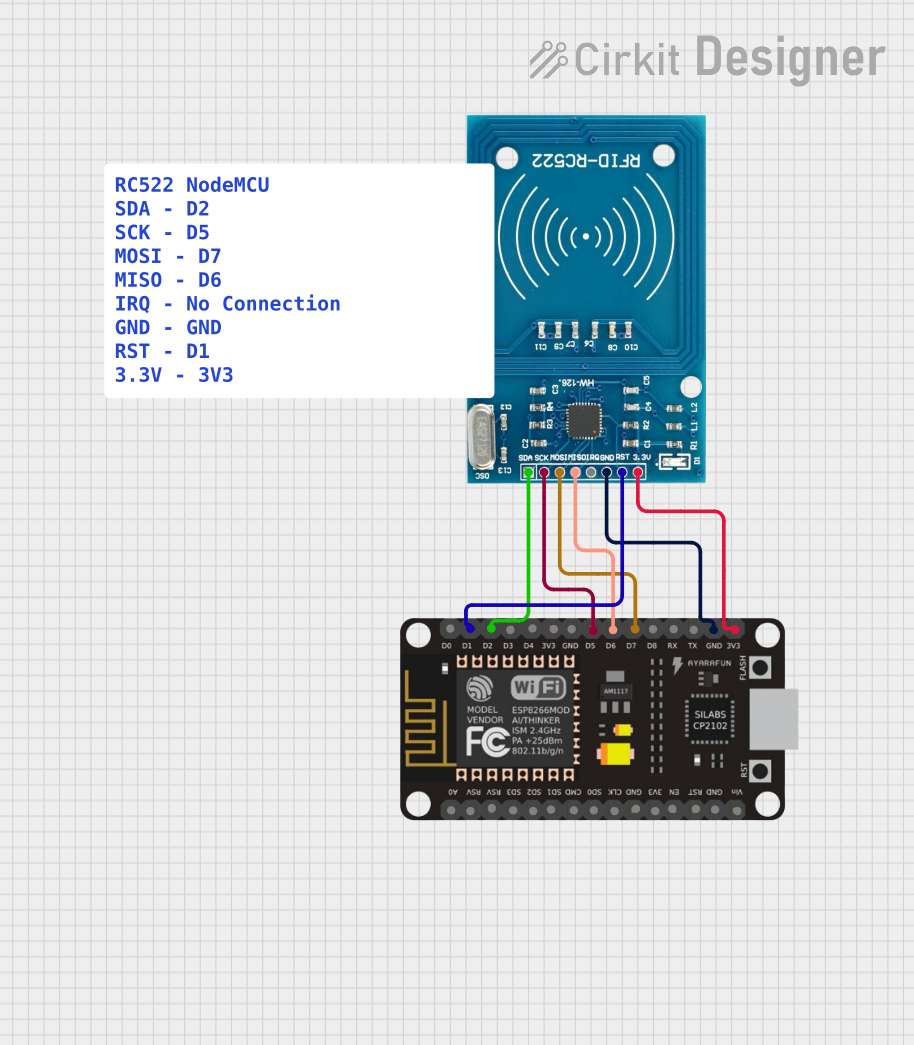
This circuit integrates an ESP8266 NodeMCU microcontroller with an RFID-RC522 reader module to create an RFID scanning system. The ESP8266 NodeMCU is responsible for controlling the RFID reader, processing the scanned RFID tags, and potentially communicating the results via its serial interface. The RFID-RC522 is powered by the 3.3V supply from the ESP8266 and communicates with the microcontroller using the SPI protocol.
Component List
ESP8266 NodeMCU
- Description: A Wi-Fi enabled microcontroller module with GPIO pins and support for serial communication.
- Pins: D0, D1, D2, D3, D4, 3V3, GND, D5, D6, D7, D8, RX, TX, A0, RSV, SD3, SD2, SD1, CMD, SD0, CLK, EN, RST, VIN
RFID-RC522
- Description: An RFID reader/writer module that operates at 13.56 MHz and uses the SPI interface for communication.
- Pins: VCC (3.3V), RST, GND, IRQ, MISO, MOSI, SCK, SDA
Comment
- Description: A placeholder for additional comments or notes within the circuit design.
Wiring Details
ESP8266 NodeMCU
- 3V3 - Provides power to the RFID-RC522 VCC (3.3V) pin.
- GND - Connected to the RFID-RC522 GND pin for a common ground reference.
- D1 - Connected to the RFID-RC522 RST pin to control the reset line.
- D2 - Connected to the RFID-RC522 SDA pin for SPI data communication.
- D5 - Connected to the RFID-RC522 SCK pin for SPI clock signal.
- D6 - Connected to the RFID-RC522 MISO pin for SPI Master In Slave Out data line.
- D7 - Connected to the RFID-RC522 MOSI pin for SPI Master Out Slave In data line.
RFID-RC522
- VCC (3.3V) - Receives power from the ESP8266 NodeMCU 3V3 pin.
- RST - Reset line controlled by the ESP8266 NodeMCU D1 pin.
- GND - Common ground with the ESP8266 NodeMCU GND pin.
- SDA - SPI data line connected to the ESP8266 NodeMCU D2 pin.
- SCK - SPI clock line connected to the ESP8266 NodeMCU D5 pin.
- MISO - SPI Master In Slave Out line connected to the ESP8266 NodeMCU D6 pin.
- MOSI - SPI Master Out Slave In line connected to the ESP8266 NodeMCU D7 pin.
Documented Code
RFID Reader Code (RFID_Reader_RC522.ino)
#include <SPI.h>
#include <MFRC522.h>

#define SS_PIN D2
#define RST_PIN D1
MFRC522 rfid(SS_PIN, RST_PIN);

void setup() {
  Serial.begin(9600);
  SPI.begin();
  rfid.PCD_Init();
  Serial.println("Scan an RFID card");
}

void loop() {
  if ( ! rfid.PICC_IsNewCardPresent()) {
    return;
  }

  if ( ! rfid.PICC_ReadCardSerial()) {
    return;
  }

  Serial.print("Card UID: ");
  for (byte i = 0; i < rfid.uid.size; i++) {
    Serial.print(rfid.uid.uidByte[i] < 0x10 ? " 0" : " ");
    Serial.print(rfid.uid.uidByte[i], HEX);
  }
  Serial.println();

  rfid.PICC_HaltA();
}
Serial Communication Web Interface (SerialCommunication.txt)
This code snippet is an HTML document with embedded JavaScript designed to facilitate serial port communication through a web interface. It allows the user to connect to a serial device, read data, and display it on the webpage.
<!DOCTYPE html>
<html lang="en">
<head>
    <meta charset="UTF-8">
    <meta name="viewport" content="width=device-width, initial-scale=1.0">
    <title>Serial Port Communication</title>
    <!-- Styles and script omitted for brevity -->
</head>
<body>
    <!-- HTML content omitted for brevity -->
    <script>
        // JavaScript code omitted for brevity
    </script>
</body>
</html>
Note: The full HTML and JavaScript code is not included in this document due to its length and complexity. The provided snippet is a placeholder to indicate where the actual code would be placed in the documentation.