
Arduino Mega 2560-Based Smart Water and Temperature Monitoring System with LCD Display and Stepper Motor
View and Edit Project In Cirkit Designer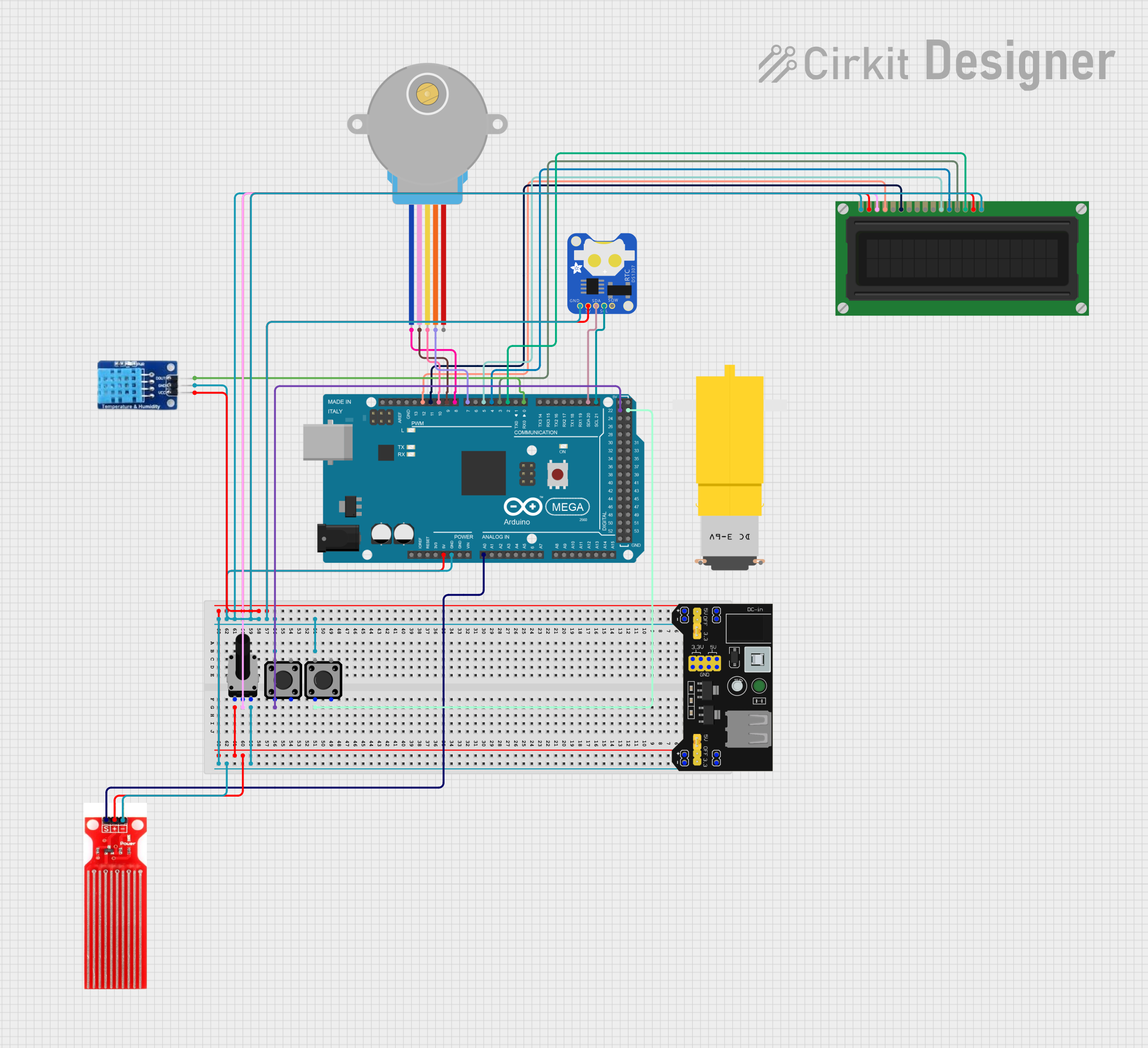
Circuit Documentation
Summary
This circuit is designed to monitor environmental conditions such as temperature and water levels, and control a stepper motor and a fan based on these conditions. The circuit uses an Arduino Mega 2560 microcontroller to interface with various sensors and actuators, including a DHT11 temperature and humidity sensor, a water sensor, a stepper motor, an LCD display, and several tactile switches. The system also includes a real-time clock (RTC) module for timekeeping.
Component List
DHT11
- Description: Temperature and Humidity Sensor
- Pins: DATA, GND, VCC
Motor amarillo motorreductor hobby
- Description: Hobby Gear Motor
- Pins: vcc, GND
28BYJ-48 Stepper Motor
- Description: Stepper Motor
- Pins: BLUE, PINK, YELLOW, ORANGE, RED
Water sensor
- Description: Water Level Sensor
- Pins: Signal, VCC, GND
Arduino Mega 2560
- Description: Microcontroller
- Pins: IOREF, RESET, 3V3, 5V, GND, VIN, A0-A15, D0-D53, AREF, SDA, SCL
Tactile Switch Buttons - 12mm Square
- Description: Push Button Switch
- Pins: 3, 1, 4, 2
DS1307 RTC (Wokwi Compatible)
- Description: Real-Time Clock Module
- Pins: GND, 5V, SDA, SCL, SQW
LCD Display (16 pin)
- Description: 16x2 Character LCD Display
- Pins: VSS, VDD, VO, RS, R_W, E, DB0-DB7, A, K
Rotary Potentiometer
- Description: Variable Resistor
- Pins: leg1, wiper, leg2
- Properties: Resistance: 10k Ohms
MB102 Breadboard Power Supply Module 3.3V/5V
- Description: Power Supply Module
- Pins: VCC, GND, 3.3V, 5V
Wiring Details
DHT11
- DATA: Connected to Arduino Mega 2560 pin D0 RX0
- GND: Connected to MB102 Breadboard Power Supply Module GND
- VCC: Connected to MB102 Breadboard Power Supply Module VCC
Motor amarillo motorreductor hobby
- vcc: Not connected in the provided net list
- GND: Not connected in the provided net list
28BYJ-48 Stepper Motor
- BLUE: Connected to Arduino Mega 2560 pin D8 PWM
- PINK: Connected to Arduino Mega 2560 pin D9 PWM
- YELLOW: Connected to Arduino Mega 2560 pin D10 PWM
- ORANGE: Connected to Arduino Mega 2560 pin D7 PWM
- RED: Not connected in the provided net list
Water sensor
- Signal: Connected to Arduino Mega 2560 pin A0
- VCC: Connected to MB102 Breadboard Power Supply Module VCC
- GND: Connected to MB102 Breadboard Power Supply Module GND
Arduino Mega 2560
- GND: Connected to MB102 Breadboard Power Supply Module GND
- 5V: Connected to MB102 Breadboard Power Supply Module VCC
- A0: Connected to Water sensor Signal
- D0 RX0: Connected to DHT11 DATA
- D2 PWM: Connected to LCD Display DB7
- D3 PWM: Connected to LCD Display DB6
- D4 PWM: Connected to LCD Display DB5
- D5 PWM: Connected to LCD Display DB4
- D7 PWM: Connected to 28BYJ-48 Stepper Motor ORANGE
- D8 PWM: Connected to 28BYJ-48 Stepper Motor BLUE
- D9 PWM: Connected to 28BYJ-48 Stepper Motor PINK
- D10 PWM: Connected to 28BYJ-48 Stepper Motor YELLOW
- D11 PWM: Connected to LCD Display E
- D12 PWM: Connected to LCD Display RS
- D20/SDA: Connected to DS1307 RTC SDA
- D21/SCL: Connected to DS1307 RTC SCL
- D22: Connected to Tactile Switch Buttons - 12mm Square pin 3
- D23: Connected to Tactile Switch Buttons - 12mm Square pin 3
Tactile Switch Buttons - 12mm Square
- Pin 3: Connected to Arduino Mega 2560 pin D23
- Pin 3: Connected to Arduino Mega 2560 pin D22
DS1307 RTC (Wokwi Compatible)
- GND: Connected to MB102 Breadboard Power Supply Module GND
- 5V: Connected to MB102 Breadboard Power Supply Module VCC
- SDA: Connected to Arduino Mega 2560 pin D20/SDA
- SCL: Connected to Arduino Mega 2560 pin D21/SCL
LCD Display (16 pin)
- VSS: Connected to MB102 Breadboard Power Supply Module GND
- VDD: Connected to MB102 Breadboard Power Supply Module VCC
- VO: Connected to Rotary Potentiometer wiper
- RS: Connected to Arduino Mega 2560 pin D12 PWM
- R_W: Not connected in the provided net list
- E: Connected to Arduino Mega 2560 pin D11 PWM
- DB0: Not connected in the provided net list
- DB1: Not connected in the provided net list
- DB2: Not connected in the provided net list
- DB3: Not connected in the provided net list
- DB4: Connected to Arduino Mega 2560 pin D5 PWM
- DB5: Connected to Arduino Mega 2560 pin D4 PWM
- DB6: Connected to Arduino Mega 2560 pin D3 PWM
- DB7: Connected to Arduino Mega 2560 pin D2 PWM
- A: Connected to MB102 Breadboard Power Supply Module VCC
- K: Connected to MB102 Breadboard Power Supply Module GND
Rotary Potentiometer
- leg1: Connected to MB102 Breadboard Power Supply Module VCC
- wiper: Connected to LCD Display VO
- leg2: Connected to MB102 Breadboard Power Supply Module GND
MB102 Breadboard Power Supply Module 3.3V/5V
- VCC: Connected to Rotary Potentiometer leg1, Water sensor VCC, DS1307 RTC 5V, DHT11 VCC, LCD Display A, LCD Display VDD, Arduino Mega 2560 5V
- GND: Connected to DS1307 RTC GND, DHT11 GND, LCD Display K, LCD Display VSS, Arduino Mega 2560 GND, Rotary Potentiometer leg2, Water sensor GND
Documented Code
#include <Wire.h>
#include <LiquidCrystal.h>
#include <RTClib.h>
#include <DHT.h>
#include <Stepper.h>

// Pin Definitions
#define WATER_SENSOR_PIN A0
#define DHT_PIN 6  // Reassigned from D2 to D6
#define FAN_PIN 3
#define YELLOW_LED_PIN 4
#define GREEN_LED_PIN 5
#define RED_LED_PIN 6
#define BLUE_LED_PIN 7
#define START_BUTTON_PIN 18
#define STOP_BUTTON_PIN 19
#define RESET_BUTTON_PIN 20

// Constants
#define DHT_TYPE DHT11
#define STEPS_PER_REV 2048
#define WATER_THRESHOLD 500  // Example threshold value
#define TEMP_THRESHOLD 25    // Example temperature threshold

// Global Variables
DHT dht(DHT_PIN, DHT_TYPE);
LiquidCrystal lcd(12, 11, 5, 4, 3, 2);
RTC_DS1307 rtc;
Stepper stepper(STEPS_PER_REV, 8, 9, 10, 7);  // Reassigned from D11 to D7

enum State { DISABLED, IDLE, ERROR, RUNNING };
State currentState = DISABLED;

void setup() {
  Serial.begin(9600);
  lcd.begin(16, 2);
  rtc.begin();
  dht.begin();
  stepper.setSpeed(10);

  pinMode(WATER_SENSOR_PIN, INPUT);
  pinMode(FAN_PIN, OUTPUT);
  pinMode(YELLOW_LED_PIN, OUTPUT