
Arduino Nano-Based Smart Energy Monitoring and Control System with Automatic Shutoff
View and Edit Project In Cirkit Designer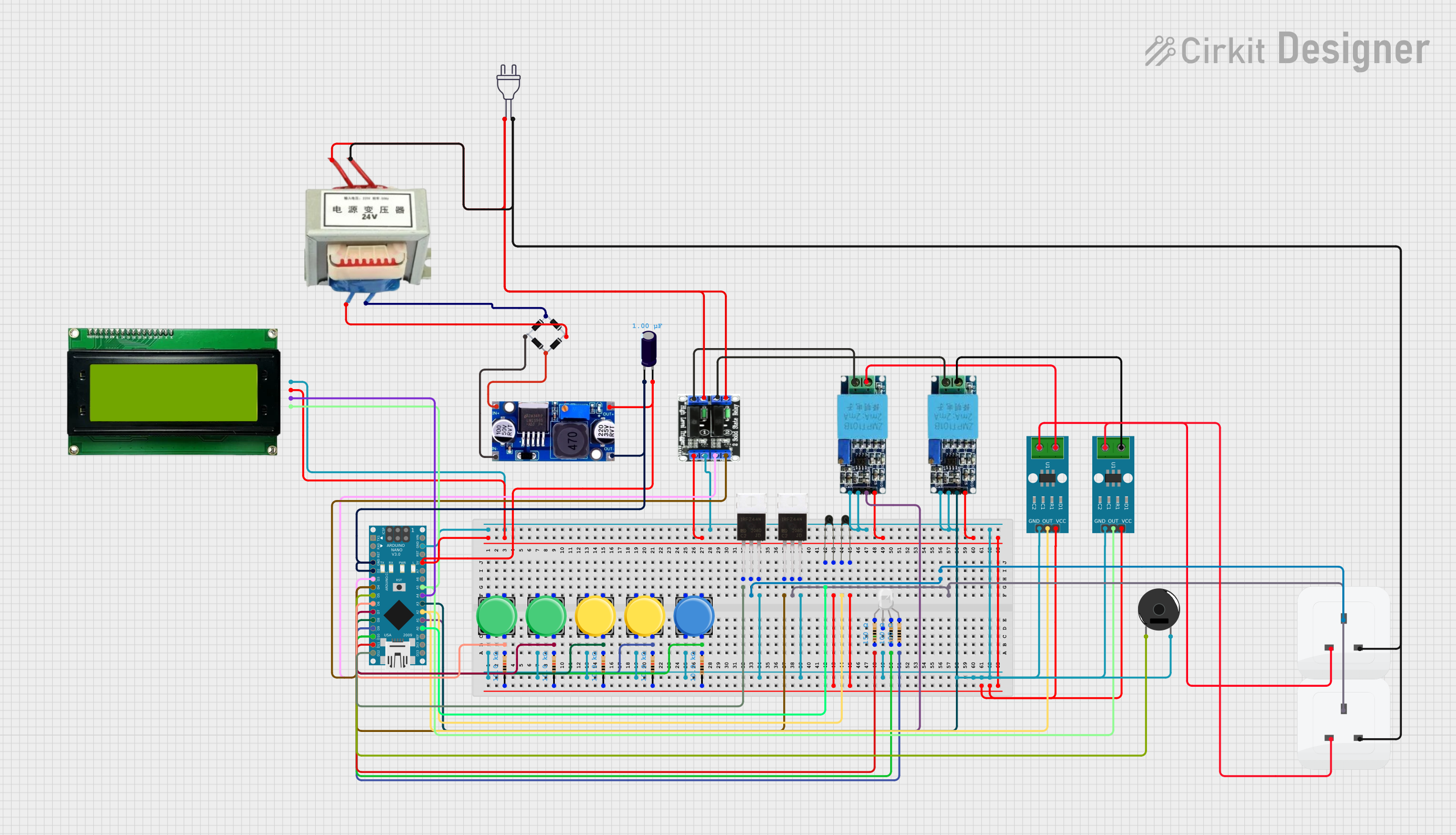
Circuit Documentation
Summary
The circuit is designed to monitor and control various parameters such as temperature, voltage, and current. It includes an Arduino Nano microcontroller interfaced with multiple sensors, a display module, pushbuttons, solid-state relays, MOSFETs, and other components. The system allows for setting thresholds and has features like alarm indication, automatic shutoff, and live monitoring displayed on an LCD.
Component List
- Arduino Nano: A compact microcontroller board based on the ATmega328P, featuring digital and analog I/O pins.
- Power 220V: The main power source for the circuit, providing 220V AC.
- LM2596: A DC-DC buck converter module used to step down voltage levels.
- Bridge Rectifier: Converts AC power from the main source to DC power.
- MKE-M08 LCD2004 I2C Module: An LCD display module with I2C communication for displaying system statuses and readings.
- Pushbuttons (x5): Used for user input to control the system and set thresholds.
- 2 Channel G3MB-202P Solid-State Relay: Allows for controlling high-power devices with low-power signals from the microcontroller.
- Voltage Sensors (x2): Measure the voltage in the circuit.
- IRFZ44N MOSFETs (x2): Power MOSFETs used for switching and controlling power to the loads.
- ACS712 Current Sensors (x2): Measure the current flowing through the circuit.
- Sockets (x2): Interface for connecting external devices to the circuit.
- NTCs (x2): Thermistors used for measuring temperature.
- RGB LED: An LED that can display multiple colors based on the input signals.
- Resistors: Various resistors used for current limiting and voltage division.
- Piezo Buzzer: An audible alarm device for alerting when thresholds are exceeded.
- Grounding Receptacle Outlet 15A 250V~: Provides a grounding connection for the circuit.
- Electrolytic Capacitor: Used for filtering and stabilizing the DC power supply.
Wiring Details
Arduino Nano
- GND: Connected to the ground plane of the circuit.
- D2-D10: Connected to pushbuttons and relay control.
- D11/MOSI, D12/MISO: Control signals for the RGB LED and MOSFETs.
- A0-A5: Analog inputs connected to NTCs, voltage sensors, and current sensors.
- 5V: Powers the LCD module, solid-state relay, voltage sensors, and current sensors.
- VIN: Receives power from the LM2596 buck converter.
Power 220V
- Hot Wire: Connected to the solid-state relay and bridge rectifier.
- Neutral Wire: Connected to the grounding receptacle outlet and sockets.
LM2596
- IN: Connected to the bridge rectifier.
- OUT: Provides regulated voltage to the Arduino Nano and other 5V components.
Bridge Rectifier
- Source_in-/+: Connected to the power 220V and grounding receptacle outlet.
- Source_out-/+: Connected to the LM2596 and grounding receptacle outlet.
MKE-M08 LCD2004 I2C Module
- GND, 5V: Power connections.
- SDA, SCL: I2C communication lines connected to the Arduino Nano.
Pushbuttons
- Pin 2: Common ground connection.
- Pin 4: Connected to the Arduino Nano digital pins with pull-up resistors.
2 Channel G3MB-202P Solid-State Relay
- DC+/-: Control input from the Arduino Nano.
- Signal Trigger 1/2: Control signals from the Arduino Nano.
- AC Hot Wire/Neutral Wire: Connected to the power 220V and voltage sensors.
Voltage Sensors
- Ground, Vcc: Power connections.
- Phase: Connected to the solid-state relay.
- Out: Analog output connected to the Arduino Nano.
IRFZ44N MOSFETs
- Gate: Control signal from the Arduino Nano.
- Drain: Connected to the sockets.
- Source: Common ground connection.
ACS712 Current Sensors
- GND, VCC: Power connections.
- OUT: Analog output connected to the Arduino Nano.
- 1, 2: Connected to the voltage sensor and socket.
Sockets
- Earth: Connected to the grounding receptacle outlet.
- Life/Neutral: Connected to the solid-state relay and current sensors.
NTCs
- A0, A1: Connected to the Arduino Nano and resistors.
RGB LED
- R, G, B: Control signals from the Arduino Nano through resistors.
- COM: Common ground connection.
Resistors
- Pin 1/2: Connected between various components and the Arduino Nano for current limiting and voltage division.
Piezo Buzzer
- Pin 1/2: Connected to the Arduino Nano for audible alerts.
Grounding Receptacle Outlet 15A 250V~
- Life/GND: Connected to the bridge rectifier and power 220V.
Electrolytic Capacitor
- +/-: Connected to the Arduino Nano for power filtering.
Documented Code
#include <Wire.h>
#include <LiquidCrystal_I2C.h>

// Pin definitions
#define BUTTON_1_PIN 6
#define BUTTON_2_PIN 7
#define BUTTON_3_PIN 8
#define BUTTON_4_PIN 9
#define BUTTON_5_PIN 10

#define RELAY_PIN 3
#define BUZZER_PIN 5
#define MOSFET_PIN 4
#define MOSFET_PIN_2 12

#define RGB_RED_PIN 11
#define RGB_GREEN_PIN 10
#define RGB_BLUE_PIN 9

// LCD initialization
LiquidCrystal_I2C lcd(0x27, 20, 4);

// Threshold variables
float tempThreshold1 = 50.0;
float voltageThreshold1 = 240.0;
float currentThreshold1 = 5.0;

float tempThreshold2 = 50.0;
float voltageThreshold2 = 240.0;
float currentThreshold2 = 5.0;

// Desired current levels
float desiredCurrent1 = 2.0;
float desiredCurrent2 = 2.0;

// Sensor readings
float temperature1 = 0.0;
float voltage1 = 0.0;
float current1 = 0.0;

float temperature2 = 0.0;
float voltage2 = 0.0;
float current2 = 0.0;

bool isSetMode = false;
bool isAlarmOn = false;
bool isAutoShutOff = false;
bool isSystemOn = true;

enum ThresholdType { TEMPERATURE, VOLTAGE, CURRENT, CURRENT_SET1, CURRENT_SET2 };
ThresholdType selectedThreshold = TEMPERATURE;

unsigned long lastThresholdChangeTime = 0;
bool thresholdChanged = false;

unsigned long lastButton5PressTime = 0;
unsigned long button5PressCount = 0;
unsigned long alarmStartTime = 0;

void setup() {
    Serial.begin(9600);

    lcd.init();
    lcd.backlight();

    // Pin mode configuration
    pinMode(RELAY_PIN, OUTPUT);
    pinMode(BUZZER_PIN, OUTPUT);
    pinMode(MOSFET_PIN, OUTPUT);
    pinMode(MOSFET_PIN_2, OUTPUT);
    pinMode(BUTTON_1_PIN, INPUT_PULLUP);
    pinMode(BUTTON_2_PIN, INPUT_PULLUP);
    pinMode(BUTTON_3_PIN, INPUT_PULLUP);
    pinMode(BUTTON_4_PIN, INPUT_PULLUP);
    pinMode(BUTTON_5_PIN, INPUT_PULLUP);

    pinMode(RGB_RED_PIN, OUTPUT);
    pinMode(RGB_GREEN_PIN, OUTPUT);
    pinMode(RGB_BLUE_PIN, OUTPUT);

    // Initial state of outputs
    digitalWrite(RELAY_PIN, LOW);
    digitalWrite(BUZZER_PIN, LOW);
    analogWrite(MOSFET_PIN, 0);
    analogWrite(MOSFET_PIN_2, 0);

    setRGBColor(0, 0, 255); // Set initial color to blue (Set Mode)
}

void loop() {
    // Button handling
    if (digitalRead(BUTTON_4_PIN) == LOW) {
        isSetMode = !isSetMode;
        delay(200); // Debounce delay
    }

    if (digitalRead(BUTTON_1_PIN) == LOW) {
        increaseThreshold();
        delay(200); // Debounce delay
    }

    if (digitalRead(BUTTON_2_PIN) == LOW) {
        decreaseThreshold();
        delay(200); // Debounce delay
    }

    if (digitalRead(BUTTON_3_PIN) == LOW) {
        switchThresholdType();
        delay(200); // Debounce delay
    }

    if (digitalRead(BUTTON_5_PIN) == LOW) {
        handleButton5Press();
        delay(200); // Debounce delay
    }

    // Mode handling
    if (isSetMode) {
        setRGBColor(0, 0, 255); // Blue for Set Mode
        displaySetMode();
    } else {
        // Read sensors
        temperature1 = readTemperature(A0);
        voltage1 = readVoltage(A1);
        current1 = readCurrent(A2