
ESP32-Based Wi-Fi Controlled PWM Fan with Temperature Regulation
View and Edit Project In Cirkit Designer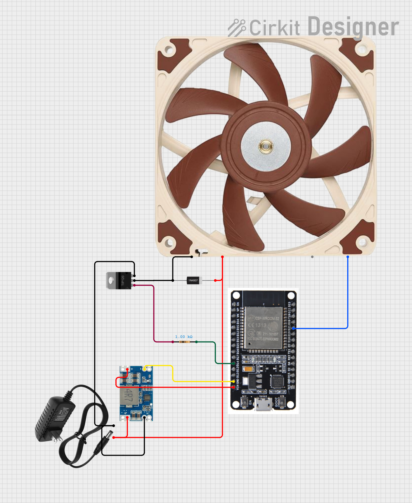
Circuit Documentation
Summary
This circuit is designed to control a 12V PWM fan using an ESP32 microcontroller. The circuit includes a TIP120 Darlington transistor to switch the fan, a 1N4007 rectifier diode for protection, a resistor to limit current, and a Mini 560 step-down converter to provide 5V power to the ESP32. The ESP32 is used to generate PWM signals to control the fan speed.
Component List
Resistor
- Description: 1k Ohm resistor
- Pins: pin1, pin2
- Properties:
- Resistance: 1000 Ohms
1N4007 Rectifier Diode
- Description: General-purpose rectifier diode
- Pins: Cathode, Anode
TIP120 Hi-Current Darlington Transistor
- Description: NPN Darlington transistor
- Pins: BASE, COLLECTOR, EMITTER
12V PWM Fan (120mm)
- Description: 12V DC fan with PWM control
- Pins: GND, +12V, TACH, PWM
ESP32
- Description: Microcontroller with Wi-Fi and Bluetooth capabilities
- Pins: EN, VP, VN, D34, D35, D32, D33, D25, D26, D27, D14, D12, D13, GND, VIN, 3V3, D15, D2, D4, RX2, TX2, D5, D18, D19, D21, RX0, TX0, D22, D23, BOOT
12V Power Supply
- Description: Provides 12V DC power
- Pins: +, -
Mini 560 Step Down 20-7V to 5V
- Description: Step-down converter to provide 5V from 12V input
- Pins: IN-, IN+, OUT-, OUT+
Wiring Details
Resistor
- pin1 is connected to the BASE of the TIP120 Hi-Current Darlington Transistor.
- pin2 is connected to D14 of the ESP32.
1N4007 Rectifier Diode
- Cathode is connected to IN+ of the Mini 560 Step Down 20-7V to 5V, +12V of the 12V PWM Fan (120mm), and + of the 12V Power Supply.
- Anode is connected to GND of the 12V PWM Fan (120mm) and COLLECTOR of the TIP120 Hi-Current Darlington Transistor.
TIP120 Hi-Current Darlington Transistor
- BASE is connected to pin1 of the Resistor.
- COLLECTOR is connected to Anode of the 1N4007 Rectifier Diode.
- EMITTER is connected to IN- of the Mini 560 Step Down 20-7V to 5V and - of the 12V Power Supply.
12V PWM Fan (120mm)
- GND is connected to Anode of the 1N4007 Rectifier Diode.
- +12V is connected to Cathode of the 1N4007 Rectifier Diode.
- PWM is connected to D21 of the ESP32.
ESP32
- D14 is connected to pin2 of the Resistor.
- D21 is connected to PWM of the 12V PWM Fan (120mm).
- GND is connected to OUT- of the Mini 560 Step Down 20-7V to 5V.
- VIN is connected to OUT+ of the Mini 560 Step Down 20-7V to 5V.
12V Power Supply
- + is connected to Cathode of the 1N4007 Rectifier Diode.
- - is connected to EMITTER of the TIP120 Hi-Current Darlington Transistor and IN- of the Mini 560 Step Down 20-7V to 5V.
Mini 560 Step Down 20-7V to 5V
- IN+ is connected to Cathode of the 1N4007 Rectifier Diode.
- IN- is connected to EMITTER of the TIP120 Hi-Current Darlington Transistor and - of the 12V Power Supply.
- OUT- is connected to GND of the ESP32.
- OUT+ is connected to VIN of the ESP32.
Code
No code is provided for this circuit.