Cirkit Designer
Your all-in-one circuit design IDE
Home /
Project Documentation
Arduino-Controlled Robotics Platform with Bluetooth Interface and Servo Actuation
Circuit Documentation
Summary
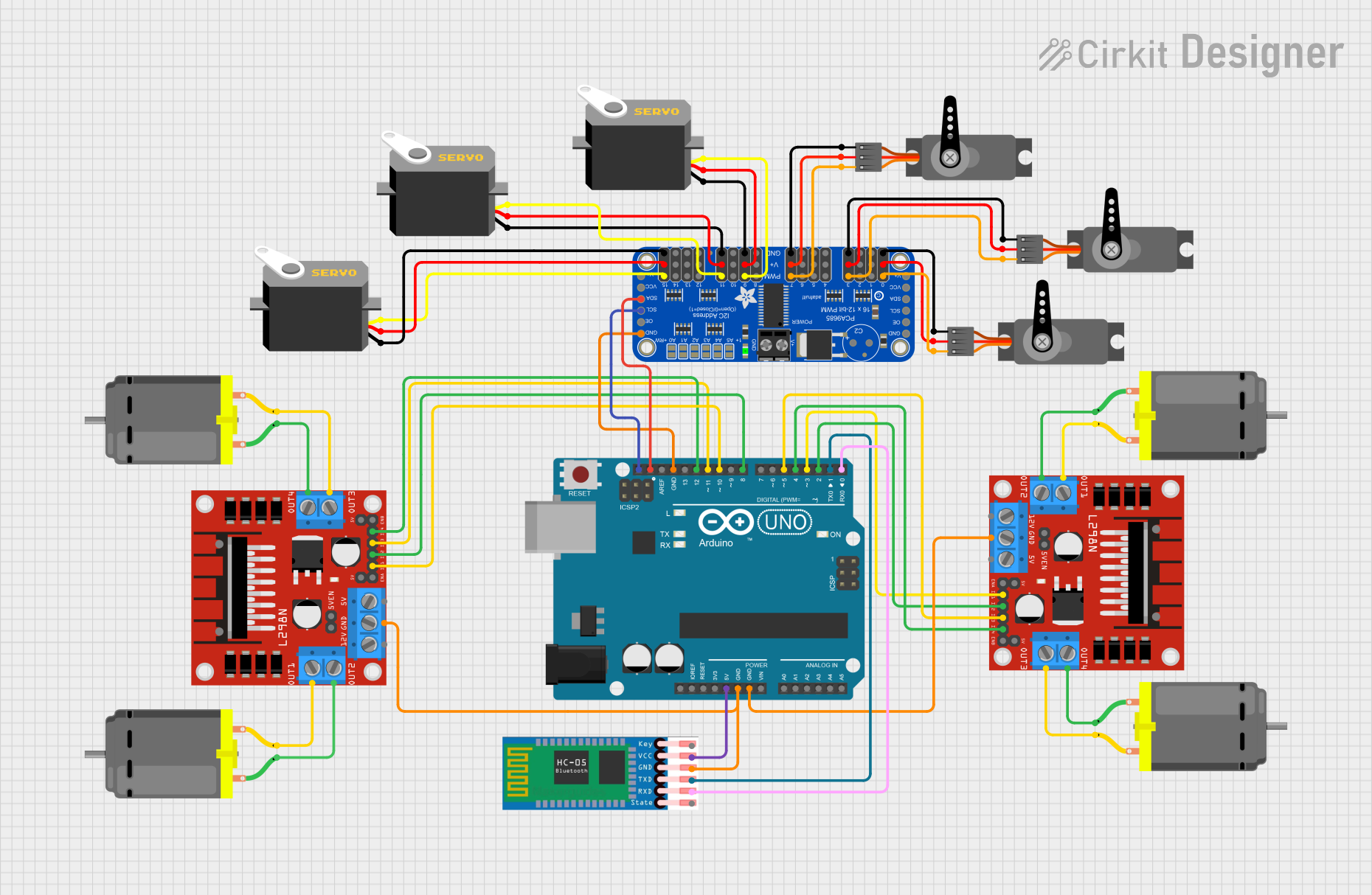
This circuit is designed to control multiple DC motors and servos using an Arduino UNO microcontroller and an L298N DC motor driver. It also includes an HC-05 Bluetooth module for wireless communication and an Adafruit PCA9685 PWM Servo Breakout to manage multiple servo motors. The circuit is powered by the Arduino UNO's 5V output, and ground connections are shared across the components.
Component List
L298N DC Motor Driver
- Description: A module capable of driving two DC motors with control over speed and direction.
- Pins: OUT1, OUT2, 12V, GND, 5V, OUT3, OUT4, 5V-ENA-JMP-I, 5V-ENA-JMP-O, +5V-J1, +5V-J2, ENA, IN1, IN2, IN3, IN4, ENB
DC Motor
- Description: An electric motor that runs on direct current (DC) electricity.
- Pins: pin 1, pin 2
Arduino UNO
- Description: A microcontroller board based on the ATmega328P.
- Pins: UNUSED, IOREF, Reset, 3.3V, 5V, GND, Vin, A0, A1, A2, A3, A4, A5, SCL, SDA, AREF, D13, D12, D11, D10, D9, D8, D7, D6, D5, D4, D3, D2, D1, D0
HC-05 Bluetooth Module
- Description: A Bluetooth module for wireless communication.
- Pins: EN, VCC, GND, TXD, RXD, STATE
Adafruit PCA9685 PWM Servo Breakout
- Description: A 16-channel, 12-bit PWM Fm+ I2C-bus LED controller optimized for driving servos.
- Pins: 5.0V, GND, PWRIN, PWM7, PWM6, PWM5, PWM4, PWM3, PWM2, PWM1, PWM0, VCC, SDA, SCL, OE, PWM15, PWM14, PWM13, PWM12, PWM11, PWM10, PWM9, PWM8
Servo
- Description: A rotary actuator or linear actuator that allows for precise control of angular or linear position.
- Pins: GND, VCC, PWM/pulse
Wiring Details
L298N DC Motor Driver
- GND connected to Arduino UNO GND
- IN1, IN2, IN3, IN4 connected to Arduino UNO digital pins (D2, D3, D4, D5 for one driver and D8, D10, D11, D12 for the other)
- OUT1, OUT2, OUT3, OUT4 connected to DC Motor pins
DC Motor
- pin 1 and pin 2 connected to L298N DC Motor Driver OUT pins
Arduino UNO
- 5V connected to HC-05 VCC and Adafruit PCA9685 5.0V
- GND connected to HC-05 GND, L298N DC Motor Driver GND, and Adafruit PCA9685 GND
- SCL connected to Adafruit PCA9685 SCL
- SDA connected to Adafruit PCA9685 SDA
- D0, D1 connected to HC-05 RXD, TXD
- D2, D3, D4, D5, D8, D10, D11, D12 connected to L298N DC Motor Driver IN pins
HC-05 Bluetooth Module
- VCC connected to Arduino UNO 5V
- GND connected to Arduino UNO GND
- TXD connected to Arduino UNO D1
- RXD connected to Arduino UNO D0
Adafruit PCA9685 PWM Servo Breakout
- 5.0V connected to Arduino UNO 5V and Servo VCC
- GND connected to Arduino UNO GND and Servo GND
- SCL connected to Arduino UNO SCL
- SDA connected to Arduino UNO SDA
- PWM outputs connected to Servo PWM/pulse pins
Servo
- GND connected to Adafruit PCA9685 GND
- VCC connected to Adafruit PCA9685 5.0V
- PWM/pulse connected to Adafruit PCA9685 PWM outputs
Documented Code
Arduino UNO Code (sketch.ino)
void setup() {
  // put your setup code here, to run once:

}

void loop() {
  // put your main code here, to run repeatedly:

}
Additional Notes (documentation.txt)
No additional code documentation provided.