
Circuit Documentation
Summary
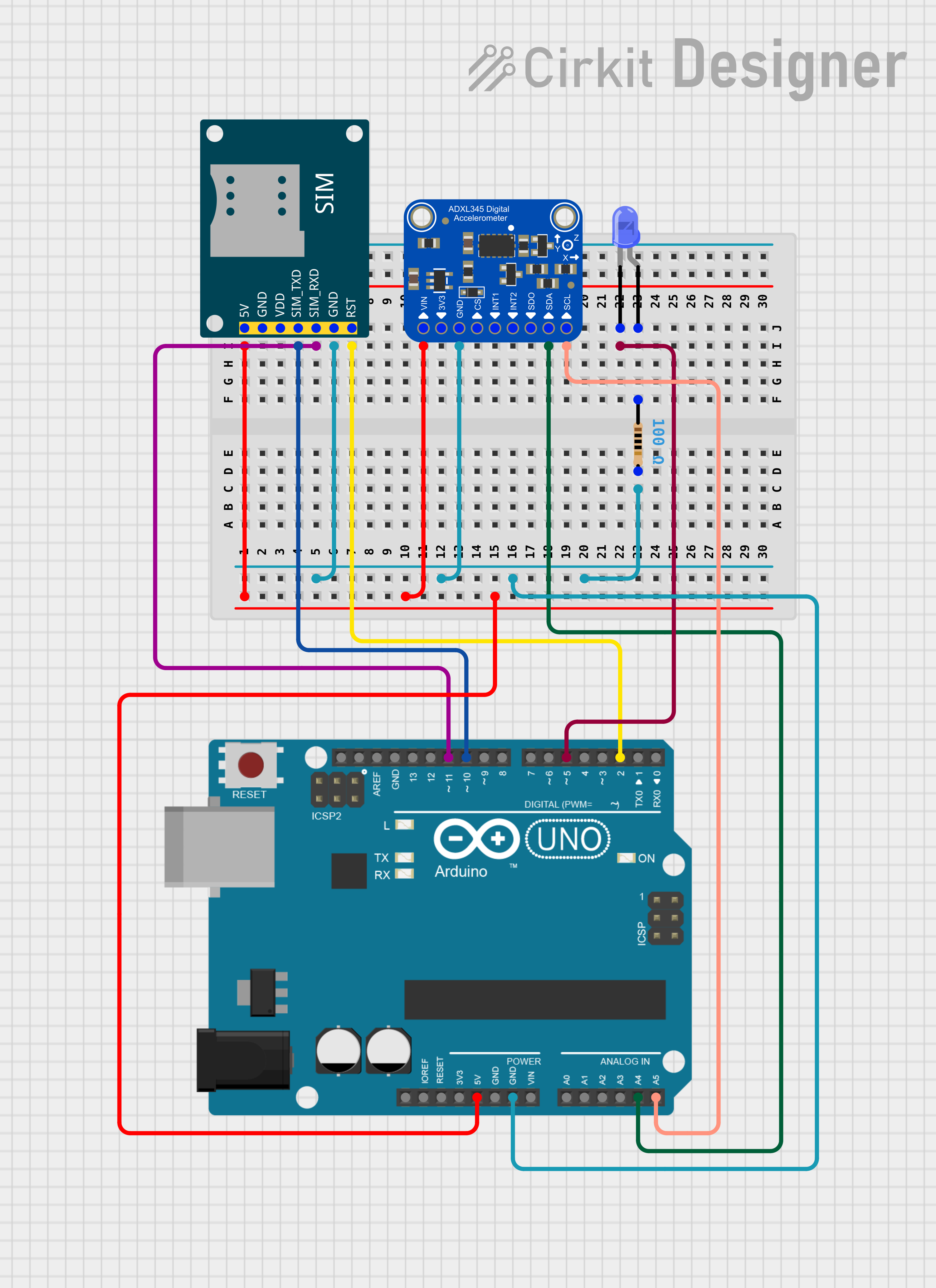
This circuit integrates an Arduino UNO microcontroller with an Adafruit ADXL345 accelerometer, a SIM800L GSM module, and a blue LED with a current-limiting resistor. The Arduino UNO is used as the central processing unit, interfacing with the accelerometer for motion detection and the GSM module for communication purposes. The LED serves as an indicator, and the resistor ensures safe operation of the LED. The embedded code on the Arduino UNO is responsible for initializing the accelerometer and GSM module, detecting a fall condition based on accelerometer data, and sending an SMS alert when such a condition is detected.
Component List
Arduino UNO
- Microcontroller board based on the ATmega328P
- Features digital I/O pins, analog input pins, and various power pins
- Utilized for controlling the accelerometer, GSM module, and LED
Adafruit ADXL345
- A small, thin, low power, 3-axis accelerometer with high resolution (13-bit) measurement
- Can measure the static acceleration of gravity in tilt-sensing applications, as well as dynamic acceleration resulting from motion or shock
- Interfaced with the Arduino UNO via I2C
SIM800L GSM Module
- A complete Quad-band GSM/GPRS solution in an LGA package
- Can be used for SMS, Data, and other GSM communications
- Connected to the Arduino UNO for sending SMS alerts
LED: Two Pin (blue)
- A basic blue light-emitting diode
- Used as an indicator light in the circuit
Resistor (100 Ohms)
- A passive two-terminal electrical component that implements electrical resistance as a circuit element
- In this circuit, it is used to limit the current flowing through the LED
Wiring Details
Arduino UNO
5Vconnected to the5Vpower supply of the SIM800L GSM Module andVINof the Adafruit ADXL345GNDconnected to the ground pins of the SIM800L GSM Module, Adafruit ADXL345, and one terminal of the resistorD10connected toSIM_TXDof the SIM800L GSM ModuleD11connected toSIM_RXDof the SIM800L GSM ModuleD2connected toRSTof the SIM800L GSM ModuleA4connected toSDA/SDIOof the Adafruit ADXL345A5connected toSCLof the Adafruit ADXL345D5connected to thecathodeof the LED
Adafruit ADXL345
VINconnected to5Vof the Arduino UNOGNDconnected toGNDof the Arduino UNOSDA/SDIOconnected toA4of the Arduino UNOSCLconnected toA5of the Arduino UNO
SIM800L GSM Module
5Vconnected to5Vof the Arduino UNOGNDconnected toGNDof the Arduino UNOSIM_TXDconnected toD10of the Arduino UNOSIM_RXDconnected toD11of the Arduino UNORSTconnected toD2of the Arduino UNO
LED: Two Pin (blue)
cathodeconnected toD5of the Arduino UNOanodeconnected to one terminal of the resistor
Resistor (100 Ohms)
- One terminal connected to
GNDof the Arduino UNO - The other terminal connected to the
anodeof the LED
Documented Code
#include <Wire.h>
#include <Adafruit_Sensor.h>
#include <Adafruit_ADXL345_U.h>
#include <SoftwareSerial.h>

Adafruit_ADXL345_Unified accel = Adafruit_ADXL345_Unified(12345);

SoftwareSerial gsm(11, 10);  // RX, TX for GSM Module

void setup() {
  Serial.begin(9600);
  gsm.begin(9600);

  if(!accel.begin()) {
    Serial.println("No ADXL345 sensor detected");
    while(1);
  }
  accel.setRange(ADXL345_RANGE_16_G);

  // Initialize GSM module
  gsm.println("AT"); // Test the GSM module
  delay(1000);
}

void sendSMS() {
  gsm.println("AT+CMGF=1");  // Set SMS mode to text
  delay(100);
  gsm.println("AT+CMGS=\"+919664939499\"");  // Replace with your phone number
  delay(100);
  gsm.print("Fall Detected!");  // Message content
  delay(100);
  gsm.write(26);  // Send Ctrl+Z to end SMS
  delay(1000);
}

void loop() {
  sensors_event_t event;
  accel.getEvent(&event);

  // Detect fall condition
  if (abs(event.acceleration.x) > 10 || abs(event.acceleration.y) > 10 || abs(event.acceleration.z) < 2) {
    sendSMS();  // Send SMS when fall is detected
    delay(5000);  // Prevent multiple SMS from being sent too frequently
  }
}
This code is designed to run on the Arduino UNO and utilizes the Adafruit ADXL345 accelerometer to detect fall conditions. When a fall is detected, it sends an SMS message using the SIM800L GSM module. The SoftwareSerial library is used to communicate with the GSM module on digital pins 10 and 11. The accelerometer is initialized and checked for presence in the setup() function. The loop() function continuously reads the accelerometer data and checks for a fall condition, defined by specific thresholds of acceleration. If a fall is detected, the sendSMS() function is called to send an alert message.