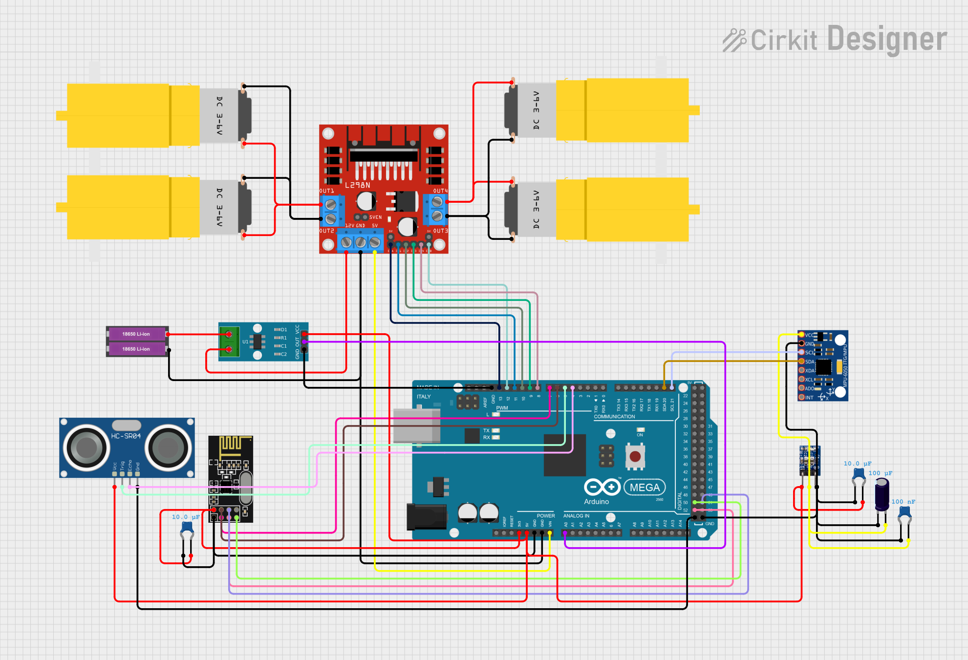
Arduino Mega 2560-Controlled Robotic Vehicle with Wireless Communication and Sensor Integration

Circuit Documentation
Summary
This circuit integrates various components including sensors, a microcontroller, communication modules, motor drivers, and power management modules to create a complex system capable of sensing, processing, and actuating. The central processing unit is an Arduino Mega 2560, which interfaces with an NRF24L01 wireless module, an MPU-6050 accelerometer and gyroscope, an HC-SR04 ultrasonic sensor, an ACS712 current sensor, and an L298N motor driver to control four hobby motors. Power management is handled by an AMS1117 3.3V voltage regulator and two 18650 Li-ion batteries. Capacitors are used throughout the circuit for stability and noise reduction.
Component List
- NRF24L01: A wireless communication module for short-range communication.
- MPU-6050: A six-axis gyroscope and accelerometer module for motion tracking.
- Ceramic Capacitor: Used for noise reduction and power supply stabilization.
- Motor Amarillo Motorreductor Hobby: A DC motor for driving mechanical parts.
- Electrolytic Capacitor: Used for power supply smoothing.
- HC-SR04 Ultrasonic Sensor: A sensor for measuring distance via ultrasonic waves.
- Arduino Mega 2560: A microcontroller board based on the ATmega2560, used as the main controller.
- AMS1117 3.3: A voltage regulator that provides a 3.3V output.
- ACS712 Current Sensor: A sensor for measuring electric current in a circuit.
- 18650 Li-ion Battery x 2: A power source for the circuit.
- L298N DC Motor Driver: A module for controlling DC motors with direction and speed control.
Wiring Details
NRF24L01
- VCC (3V) connected to Arduino Mega 2560 (3V3)
- GND connected to common ground
- CSN connected to Arduino Mega 2560 (D6 PWM)
- CE connected to Arduino Mega 2560 (D7 PWM)
- SCK connected to Arduino Mega 2560 (D52)
- MISO connected to Arduino Mega 2560 (D50)
- MOSI connected to Arduino Mega 2560 (D51)
MPU-6050
- VCC connected to AMS1117 3.3 (OUT)
- GND connected to common ground
- SCL connected to Arduino Mega 2560 (D21/SCL)
- SDA connected to Arduino Mega 2560 (D20/SDA)
Ceramic Capacitors
- Connected across power lines (VCC and GND) near various components for noise reduction.
Motor Amarillo Motorreductor Hobby
- Four motors connected to L298N DC motor driver (OUT1, OUT2, OUT3, OUT4)
Electrolytic Capacitor
- Connected across AMS1117 3.3 (OUT) and ground for power smoothing.
HC-SR04 Ultrasonic Sensor
- VCC connected to Arduino Mega 2560 (5V)
- GND connected to common ground
- TRIG connected to Arduino Mega 2560 (D5 PWM)
- ECHO connected to Arduino Mega 2560 (D4 PWM)
Arduino Mega 2560
- Acts as the central controller for the circuit.
- Various I/O pins connected to sensors and modules as detailed above.
- VIN connected to L298N DC motor driver (5V)
- GND connected to common ground
AMS1117 3.3
- VIN connected to Arduino Mega 2560 (5V)
- OUT connected to MPU-6050 (VCC) and other components requiring 3.3V
- GND connected to common ground
ACS712 Current Sensor
- VCC connected to Arduino Mega 2560 (5V)
- GND connected to common ground
- OUT connected to Arduino Mega 2560 (A0)
18650 Li-ion Battery x 2
- Provides power to the circuit.
- Positive terminal connected to ACS712 Current Sensor (1)
- Negative terminal connected to common ground
L298N DC Motor Driver
- IN1, IN2, IN3, IN4 connected to Arduino Mega 2560 (D11 PWM, D10 PWM, D9 PWM, D8 PWM)
- ENA, ENB connected to Arduino Mega 2560 (D13 PWM, D12 PWM)
- OUT1, OUT2, OUT3, OUT4 connected to motors
- 12V connected to ACS712 Current Sensor (2)
- 5V connected to Arduino Mega 2560 (VIN)
- GND connected to common ground
Documented Code
Arduino Mega 2560 Code (sketch.ino)
void setup() {
  // put your setup code here, to run once:

}

void loop() {
  // put your main code here, to run repeatedly:

}
This code is a template for the Arduino Mega 2560. The setup() function runs once when the microcontroller is reset or powered on, and the loop() function runs repeatedly, allowing the microcontroller to perform tasks, read sensors, and control actuators. The actual implementation details will depend on the specific requirements of the application.