
Raspberry Pi Pico Heart Rate Monitor with Reed Switch and Buzzer
View and Edit Project In Cirkit Designer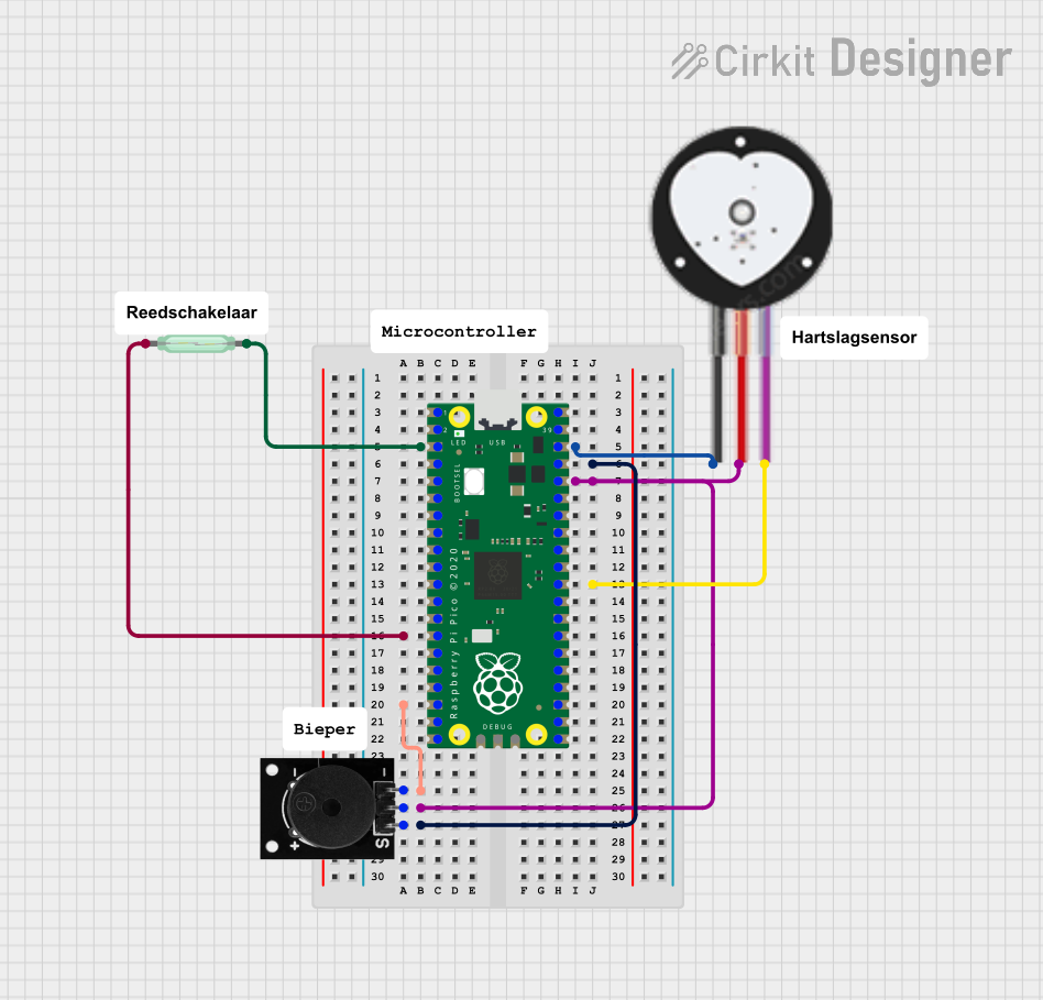
Circuit Documentation
Summary
This circuit involves a Raspberry Pi Pico microcontroller interfacing with a Heart Pulse Sensor, a Reed Switch, and a Passive Buzzer. The Raspberry Pi Pico reads signals from the Heart Pulse Sensor and the Reed Switch, and it controls the Passive Buzzer. The circuit is designed to monitor heart pulse and detect the state of the Reed Switch, potentially triggering the buzzer based on certain conditions.
Component List
Raspberry Pi Pico
- Description: A low-cost, high-performance microcontroller board with flexible digital interfaces.
- Pins: 43 GPIO pins
Heart Pulse Sensor
- Description: A sensor used to measure the heart rate.
- Pins: GND, VCC, SIGNAL
Reed Switch
- Description: A magnetic switch used to detect the presence of a magnetic field.
- Pins: pin 1, pin 2
Passive Buzzer
- Description: A simple buzzer that produces sound when a voltage is applied.
- Pins: S output signal, +VCC, GND
Wiring Details
Raspberry Pi Pico
- pin 3 is connected to Reed Switch pin 2
- pin 14 is connected to Reed Switch pin 1
- pin 18 is connected to Passive Buzzer GND
- pin 30 is connected to Heart Pulse Sensor SIGNAL
- pin 36 is connected to Passive Buzzer +VCC and Heart Pulse Sensor VCC
- pin 37 is connected to Passive Buzzer S output signal
- pin 38 is connected to Heart Pulse Sensor GND
Heart Pulse Sensor
- GND is connected to Raspberry Pi Pico pin 38
- VCC is connected to Raspberry Pi Pico pin 36
- SIGNAL is connected to Raspberry Pi Pico pin 30
Reed Switch
- pin 1 is connected to Raspberry Pi Pico pin 14
- pin 2 is connected to Raspberry Pi Pico pin 3
Passive Buzzer
- S output signal is connected to Raspberry Pi Pico pin 37
- +VCC is connected to Raspberry Pi Pico pin 36
- GND is connected to Raspberry Pi Pico pin 18
Documented Code
sketch.ino
void setup() {
  // put your setup code here, to run once:

}

void loop() {
  // put your main code here, to run repeatedly:

}
documentation.txt