
Arduino UNO Gas Leak Detection System with Servo Control and Alarm
View and Edit Project In Cirkit Designer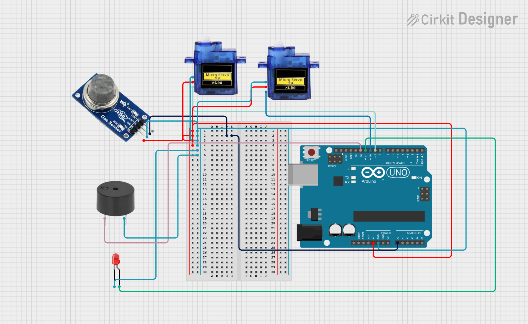
Circuit Documentation
Summary
This circuit involves an Arduino UNO microcontroller interfaced with an MQ2 gas sensor, two micro servo motors, a red LED, and a buzzer. The circuit is designed to monitor gas levels using the MQ2 sensor and trigger actions such as lighting an LED, sounding a buzzer, and moving servo motors when gas levels exceed a certain threshold.
Component List
Arduino UNO
- Description: A microcontroller board based on the ATmega328P.
- Pins: UNUSED, IOREF, Reset, 3.3V, 5V, GND, Vin, A0, A1, A2, A3, A4, A5, SCL, SDA, AREF, D13, D12, D11, D10, D9, D8, D7, D6, D5, D4, D3, D2, D1, D0
MQ2 Gas Sensor
- Description: A gas sensor module used to detect gas levels.
- Pins: VCC, GND, AOUT, DOUT
Micro Servo 9G (Servo 1)
- Description: A small servo motor used for precise control of angular position.
- Pins: GND, +5V, PWM
Micro Servo 9G (Servo 2)
- Description: A small servo motor used for precise control of angular position.
- Pins: GND, +5V, PWM
LED: Two Pin (Red)
- Description: A red LED used for visual indication.
- Pins: cathode, anode
Buzzer
- Description: A buzzer used for audible alerts.
- Pins: PIN, GND
Wiring Details
Arduino UNO
- 5V: Connected to VCC of MQ2, +5V of Servo 1, +5V of Servo 2
- GND: Connected to GND of MQ2, GND of Servo 1, GND of Servo 2, cathode of LED, GND of Buzzer
- A0: Connected to AOUT of MQ2
- D12: Connected to PIN of Buzzer
- D11: Connected to anode of LED
- D10: Connected to PWM of Servo 1
- D9: Connected to PWM of Servo 2
MQ2 Gas Sensor
- VCC: Connected to 5V of Arduino UNO
- GND: Connected to GND of Arduino UNO
- AOUT: Connected to A0 of Arduino UNO
Micro Servo 9G (Servo 1)
- GND: Connected to GND of Arduino UNO
- +5V: Connected to 5V of Arduino UNO
- PWM: Connected to D10 of Arduino UNO
Micro Servo 9G (Servo 2)
- GND: Connected to GND of Arduino UNO
- +5V: Connected to 5V of Arduino UNO
- PWM: Connected to D9 of Arduino UNO
LED: Two Pin (Red)
- cathode: Connected to GND of Arduino UNO
- anode: Connected to D11 of Arduino UNO
Buzzer
- PIN: Connected to D12 of Arduino UNO
- GND: Connected to GND of Arduino UNO
Code Documentation
#include <Servo.h>

Servo servo1;
Servo servo2;

const int mq2Pin = A0;  // MQ-2 sensor connected to A0
const int ledPin = 11;   // LED connected to pin 11
const int buzzerPin = 12; // Buzzer connected to pin 12

void setup() {
  Serial.begin(9600);
  servo1.attach(9);  // Attach servo 1 to pin 9
  servo2.attach(10); // Attach servo 2 to pin 10

  pinMode(ledPin, OUTPUT);
  pinMode(buzzerPin, OUTPUT);

  // Initialize servos to 0 degrees
  servo1.write(0);
  servo2.write(0);
}

void loop() {
  int mq2Value = analogRead(mq2Pin); // Read the value from the MQ-2 sensor
  Serial.println(mq2Value); // Print the sensor value to the serial monitor

  // Check the MQ-2 sensor value to determine actions
  if (mq2Value > 300) { // Adjust threshold as necessary
    digitalWrite(ledPin, HIGH); // Turn on LED
    digitalWrite(buzzerPin, HIGH); // Turn on Buzzer
    servo1.write(90); // Move servo 1 to 90 degrees
    servo2.write(90); // Move servo 2 to 90 degrees
  } else {
    digitalWrite(ledPin, LOW); // Turn off LED
    digitalWrite(buzzerPin, LOW); // Turn off Buzzer
    servo1.write(0); // Move servo 1 back to 0 degrees
    servo2.write(0); // Move servo 2 back to 0 degrees
  }

  delay(1000); // Delay for a second before reading again
}
This code initializes the components and continuously reads the gas level from the MQ2 sensor. If the gas level exceeds a threshold, it activates the LED, buzzer, and moves the servos to 90 degrees. If the gas level is below the threshold, it deactivates the LED, buzzer, and returns the servos to 0 degrees.