Cirkit Designer
Your all-in-one circuit design IDE
Home /
Project Documentation
Micro:bit Controlled Traffic Light Simulation
Traffic Light System Circuit Documentation
Summary
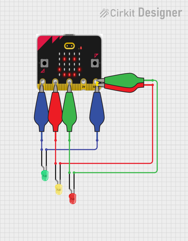
The Traffic Light System is a simple educational project that simulates a traffic light sequence using a micro:bit microcontroller and three LEDs (red, yellow, and green). The micro:bit controls the LEDs to light up in a specific order, mimicking the operation of a standard traffic light. The circuit is powered by the micro:bit, and the LEDs are connected to it via alligator clip cables.
Component List
micro:bit
- Description: A compact microcontroller board designed for education, with multiple I/O pins.
- Pins: pin 0, pin 1, pin 2, 3.3V, GND
LED: Two Pin (red)
- Description: A red LED with two pins, anode, and cathode.
LED: Two Pin (green)
- Description: A green LED with two pins, anode, and cathode.
LED: Two Pin (yellow)
- Description: A yellow LED with two pins, anode, and cathode.
Alligator Clip Cable (blue)
- Description: A blue alligator clip cable used to make temporary electrical connections.
Alligator Clip Cable (red)
- Description: A red alligator clip cable used to make temporary electrical connections.
Alligator Clip Cable (green)
- Description: A green alligator clip cable used to make temporary electrical connections.
Wiring Details
micro:bit
- GND: Connected to a blue alligator clip cable.
LED: Two Pin (red)
- Cathode: Connected to a green alligator clip cable.
- Anode: Connected to another green alligator clip cable.
LED: Two Pin (green)
- Cathode: Connected to a blue alligator clip cable.
- Anode: Connected to another blue alligator clip cable.
LED: Two Pin (yellow)
- Cathode: Connected to a red alligator clip cable.
- Anode: Connected to another red alligator clip cable.
Alligator Clip Cable (blue)
- Pin: Connects the micro:bit GND to the green LED cathode and the micro:bit 3.3V to the green LED anode.
Alligator Clip Cable (red)
- Pin: Connects the yellow LED cathode to one pin and the yellow LED anode to another pin.
Alligator Clip Cable (green)
- Pin: Connects the red LED cathode to one pin and the red LED anode to another pin.
Documented Code
/*
 * Traffic Light System
 * This code controls a traffic light system using three LEDs (red, yellow,
 * and green) connected to a micro:bit. The system cycles through the LEDs
 * to simulate a traffic light sequence.
 */

// Pin definitions
const int greenLEDPin = 0; // Pin 0 for green LED
const int yellowLEDPin = 1; // Pin 1 for yellow LED
const int redLEDPin = 2; // Pin 2 for red LED

void setup() {
  // Initialize the LED pins as outputs
  pinMode(greenLEDPin, OUTPUT);
  pinMode(yellowLEDPin, OUTPUT);
  pinMode(redLEDPin, OUTPUT);
}

void loop() {
  // Green light on for 5 seconds
  digitalWrite(greenLEDPin, HIGH);
  delay(5000);
  digitalWrite(greenLEDPin, LOW);

  // Yellow light on for 2 seconds
  digitalWrite(yellowLEDPin, HIGH);
  delay(2000);
  digitalWrite(yellowLEDPin, LOW);

  // Red light on for 5 seconds
  digitalWrite(redLEDPin, HIGH);
  delay(5000);
  digitalWrite(redLEDPin, LOW);
}
Filename: Traffic Light.ino
This code is designed to run on a micro:bit microcontroller. It sets up three pins as outputs to control the red, yellow, and green LEDs. In the main loop, it turns on each LED in sequence, with the green and red LEDs on for 5 seconds each and the yellow LED on for 2 seconds, creating a traffic light effect.