Cirkit Designer
Your all-in-one circuit design IDE
Home /
Project Documentation
ESP32-Based Plant Monitoring System with Wi-Fi Control and Relay Switching
Circuit Documentation
Summary
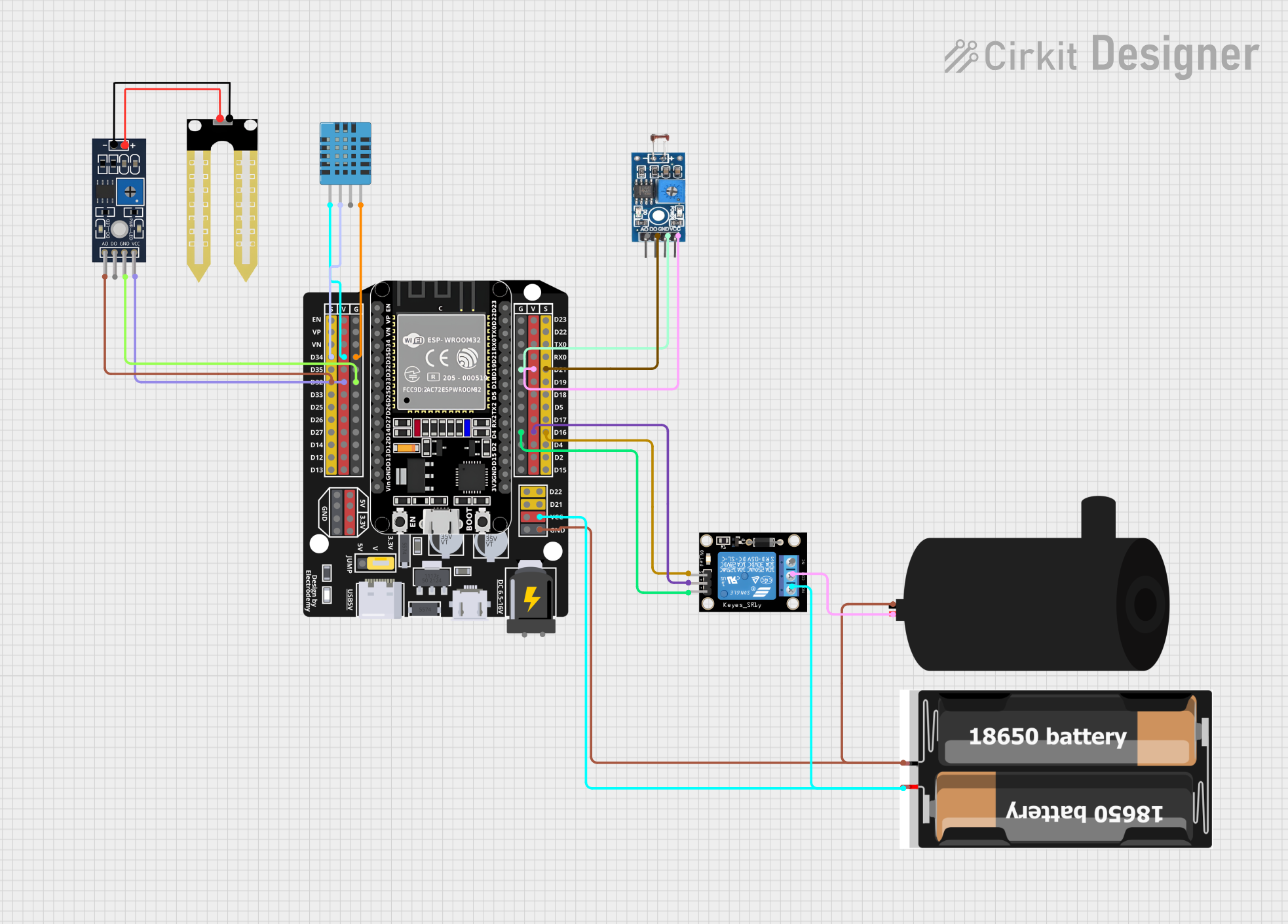
This circuit is designed for a plant monitoring system that interfaces with various sensors to measure environmental conditions such as temperature, humidity, and light intensity. It also controls a water pump via a relay module. The system is built around an ESP32 microcontroller, which is programmed to communicate with the Blynk platform for remote monitoring and control. The ESP32 reads sensor data, controls the relay, and updates the Blynk server with the sensor values. An LCD display provides local readouts of the sensor data.
Component List
Humidity YL-69 Sensor
- Pins: A0, D0, GND, VCC
- Description: A soil moisture sensor that measures the conductivity of the soil to estimate its moisture content.
Photosensitive Sensor Module
- Pins: Analog Output, Digital Output, Ground, VCC
- Description: A light sensor that detects the intensity of light in the environment.
Water Pump
- Pins: Positive, Negative
- Description: An electric pump used for watering plants.
Relay Module (1 Channel)
- Pins: S, 5V, GND, NC, COM, NO
- Description: An electrically operated switch that allows the ESP32 to control high-power devices like the water pump.
ESP32 - Expansion Board
- Pins: +, -, EN, VP, VN, D34, D32, D33, D25, D26, D27, D14, D12, D13, D23, D22, TX0, RX0, D21, D19, D18, D5, D17, D16, D4, D2, D15, VCC, G, 5V, 3.3V, V
- Description: A powerful microcontroller with Wi-Fi capabilities, used as the central processing unit of the plant monitoring system.
2x 18650 Battery Holder
- Pins: VCC, GND
- Description: A battery holder for two 18650 lithium-ion batteries, providing power to the circuit.
DHT11 Humidity and Temperature Sensor
- Pins: VDD, DATA, NULL, GND
- Description: A sensor that measures ambient temperature and humidity.
Wiring Details
Humidity YL-69 Sensor
- A0: Connected to ESP32 pin D32
- D0: Not connected
- GND: Connected to ESP32 pin G
- VCC: Connected to ESP32 pin V
Photosensitive Sensor Module
- Analog Output: Not connected
- Digital Output: Connected to ESP32 pin D21
- Ground: Connected to ESP32 pin G
- VCC: Connected to ESP32 pin V
Water Pump
- Positive: Connected to Relay Module pin COM
- Negative: Connected to 2x 18650 Battery Holder pin GND
Relay Module (1 Channel)
- S: Connected to ESP32 pin D16
- 5V: Connected to ESP32 pin V
- GND: Connected to ESP32 pin G
- NC: Not connected
- COM: Connected to Water Pump pin Positive
- NO: Connected to 2x 18650 Battery Holder pin VCC
ESP32 - Expansion Board
- D34: Connected to DHT11 Sensor pin DATA
- D32: Connected to Humidity YL-69 Sensor pin A0
- D21: Connected to Photosensitive Sensor Module pin Digital Output
- D16: Connected to Relay Module pin S
- VCC: Connected to Relay Module pin NO
- G: Connected to common ground of all components
- V: Connected to VCC of DHT11 Sensor, Humidity YL-69 Sensor, Photosensitive Sensor Module, and Relay Module
2x 18650 Battery Holder
- VCC: Connected to Relay Module pin NO
- GND: Connected to Water Pump pin Negative
DHT11 Humidity and Temperature Sensor
- VDD: Connected to ESP32 pin V
- DATA: Connected to ESP32 pin D34
- NULL: Not connected
- GND: Connected to ESP32 pin G
Documented Code
#define BLYNK_TEMPLATE_ID "TMPL6rlQf3Kxk"
#define BLYNK_TEMPLATE_NAME "plant monitoring sistem"

/* Connections
Relay: GPIO23
Btn:   GPIO27
Soil:  GPIO36 (VP)
PIR:   GPIO18
SDA:   GPIO21
SCL:   GPIO22
Temp:  GPIO19
*/

// Include the library files
#include <LiquidCrystal_I2C.h>
#define BLYNK_PRINT Serial
#include <WiFi.h>
#include <BlynkSimpleEsp32.h>
#include <DHT.h>

// Initialize the LCD display
LiquidCrystal_I2C lcd(0x3F, 16, 2);

char auth[] = "U_LC-vFWsz-x6y7oXznm5YBllNn1oHhU";  // Enter your Blynk Auth token
char ssid[] = "Redmi K50 Ultra";  // Enter your WIFI SSID
char pass[] = "12345678";  // Enter your WIFI Password

DHT dht(19, DHT22);  // (DHT sensor pin, sensor type) GPIO19 DHT22 Temperature Sensor
BlynkTimer timer;

// Define component pins
#define soil 36  // GPIO36 (VP) for Soil Moisture Sensor
#define PIR 18   // GPIO18 for PIR Motion Sensor
int PIR_ToggleValue;

void checkPhysicalButton();
int relay1State = LOW;
int pushButton1State = HIGH;
#define RELAY_PIN_1 23       // GPIO23 for Relay
#define PUSH_BUTTON_1 27     // GPIO27 for Button
#define VPIN_BUTTON_1 V12

// Create three variables for pressure
double T, P;
char status;

void setup() {
  Serial.begin(9600);
  lcd.begin(16, 2);  // Initialize the LCD with 16 columns and 2 rows
  lcd.backlight();
  pinMode(PIR, INPUT);

  pinMode(RELAY_PIN_1, OUTPUT);
  digitalWrite(RELAY_PIN_1, LOW);
  pinMode(PUSH_BUTTON_1, INPUT_PULLUP);
  digitalWrite(RELAY_PIN_1, relay1State);

  Blynk.begin(auth, ssid, pass, "blynk.cloud", 80);
  dht.begin();

  lcd.setCursor(0, 0);
  lcd.print("  Initializing  ");
  for (int a = 5; a <= 10; a++) {
    lcd.setCursor(a, 1);
    lcd.print(".");
    delay(500);
  }
  lcd.clear();
  lcd.setCursor(11, 1);
  lcd.print("W:OFF");

  // Call the function
  timer.setInterval(100L, soilMoistureSensor);
  timer.setInterval(100L, DHT22sensor);
  timer.setInterval(500L, checkPhysicalButton);
}

// Get the DHT22 sensor values
void DHT22sensor() {
  float h = dht.readHumidity();
  float t = dht.readTemperature();

  if (isnan(h) || isnan(t)) {
    Serial.println("Failed to read from DHT sensor!");
    return;
  }
  Blynk.virtualWrite(V0, t);
  Blynk.virtualWrite(V1, h);

  lcd.setCursor(0, 0);
  lcd.print("T:");
  lcd.print(t);

  lcd.setCursor(8, 0);
  lcd.print("H:");
  lcd.print(h);
}

// Get the soil moisture values
void soilMoistureSensor() {
  int value = analogRead(soil);
  value = map(value, 0, 4095, 0, 100);  // ESP32 has a 12-bit ADC
  value = (value - 100) * -1;

  Blynk.virtualWrite(V3, value);
  lcd.setCursor(0, 1);
  lcd.print("S:");
  lcd.print(value);
  lcd.print(" ");
}

// Get the PIR sensor values
void PIRsensor() {
  bool value = digitalRead(PIR);
  if (value) {
    Blynk.logEvent("pirmotion", "WARNING! Motion Detected!"); // Enter your Event Name
    WidgetLED LED(V5);
    LED.on();
  } else {
    WidgetLED LED(V5);
    LED.off();
  }
}

BLYNK_WRITE(V6)
{
 PIR_ToggleValue = param.asInt();
}

BLYNK_CONNECTED() {
  // Request the latest state from the server
  Blynk.syncVirtual(VPIN_BUTTON_1);
}

BLYNK_WRITE(VPIN_BUTTON_1) {
  relay1State = param.asInt();
  digitalWrite(RELAY_PIN_1, relay1State);
}

void checkPhysicalButton() {
  if (digitalRead(PUSH_BUTTON_1) == LOW) {
    // pushButton1State is used to avoid sequential toggles
    if (pushButton1State != LOW) {
      // Toggle Relay state
      relay1State = !relay1State;
      digitalWrite(RELAY_PIN_1