
Arduino UNO and ESP8266 WiFi-Controlled Water Pump System with Ultrasonic Sensing
View and Edit Project In Cirkit Designer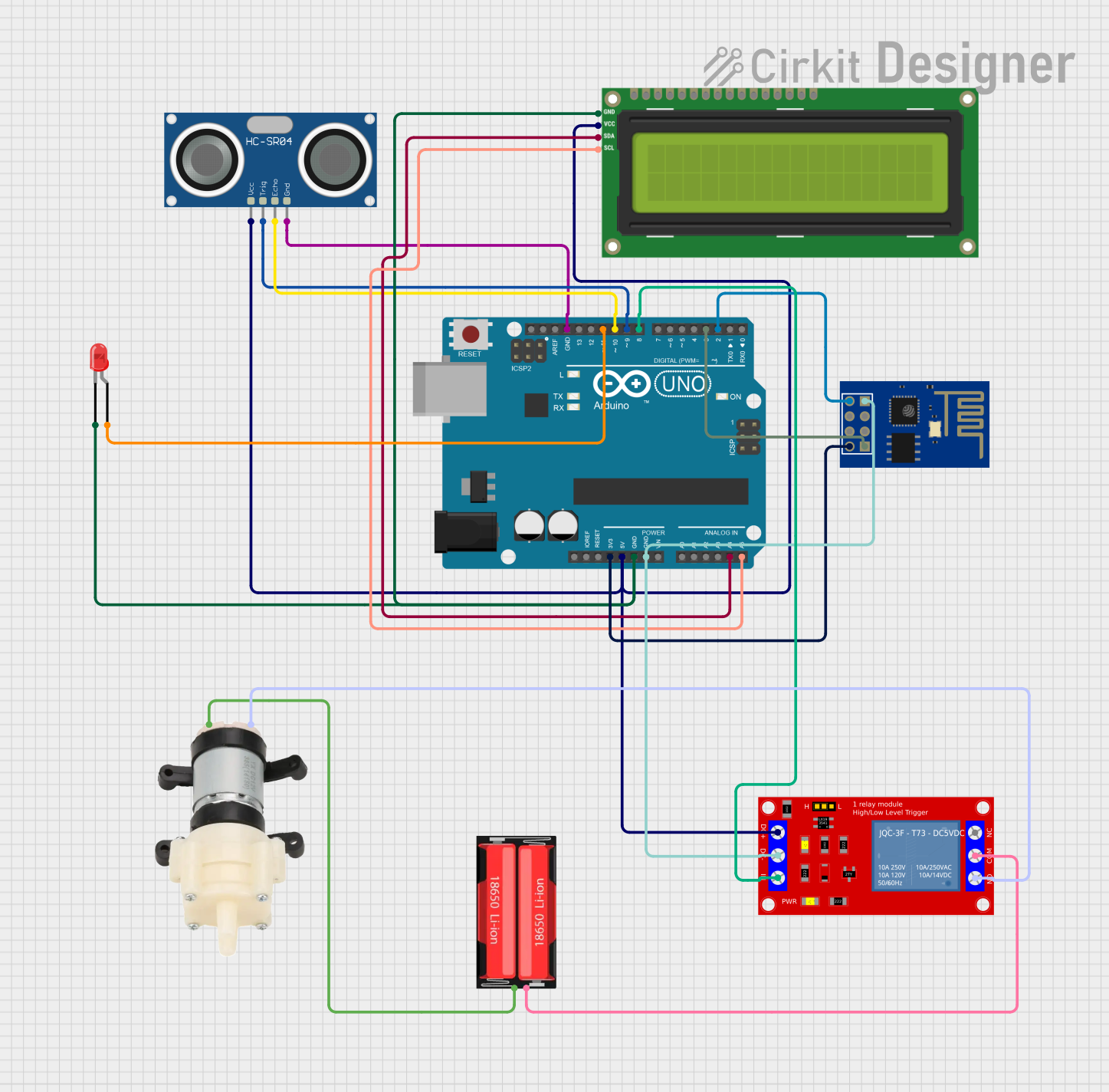
Circuit Documentation
Summary
This circuit integrates various components to create a system that likely serves as a sensor-based control unit with wireless communication capabilities. The Arduino UNO serves as the central microcontroller, interfacing with an ESP8266 ESP-01 WiFi module for network connectivity, an HC-SR04 ultrasonic sensor for distance measurement, an I2C LCD 16x2 screen for display, a 1-channel 5V relay module for controlling power to an external device (a mini diaphragm water pump in this case), and an LED for indication purposes. The circuit is powered by an 18650 Li-Ion battery.
Component List
- Arduino UNO: A microcontroller board based on the ATmega328P, featuring digital and analog I/O pins.
- ESP8266 ESP-01 WiFi Module: A WiFi module that enables the Arduino to connect to the internet.
- 18650 Li-Ion Battery: A rechargeable battery providing power to the circuit.
- HC-SR04 Ultrasonic Sensor: A sensor used for measuring distances via ultrasonic waves.
- I2C LCD 16x2 Screen: A liquid crystal display that can show 16 characters per 2 lines, interfaced via I2C.
- Mini Diaphragm Water Pump: A pump used for moving liquids, controlled by the relay module.
- 1 Channel 5V Relay Module: An electrically operated switch that allows you to turn on or off a circuit using voltage and/or current much higher than a microcontroller can handle.
- LED (Red, Two Pin): A basic red light-emitting diode used for indication.
Wiring Details
Arduino UNO
- 3.3V connected to ESP8266 ESP-01 WiFi Module VCC
- 5V connected to:
- I2C LCD 16x2 Screen VCC (5V)
- HC-SR04 Ultrasonic Sensor VCC
- 1 Channel 5V Relay Module VCC+
- GND connected to:
- I2C LCD 16x2 Screen GND
- LED (Red, Two Pin) cathode
- ESP8266 ESP-01 WiFi Module GND
- 1 Channel 5V Relay Module VCC- (GND)
- HC-SR04 Ultrasonic Sensor GND
- A4 (SDA) connected to I2C LCD 16x2 Screen SDA
- A5 (SCL) connected to I2C LCD 16x2 Screen SCL
- D11 connected to LED (Red, Two Pin) anode
- D10 connected to HC-SR04 Ultrasonic Sensor ECHO
- D9 connected to HC-SR04 Ultrasonic Sensor TRIG
- D8 connected to 1 Channel 5V Relay Module IN
- D3 connected to ESP8266 ESP-01 WiFi Module RXD
- D2 connected to ESP8266 ESP-01 WiFi Module TXD
ESP8266 ESP-01 WiFi Module
- VCC connected to Arduino UNO 3.3V
- GND connected to Arduino UNO GND
- RXD connected to Arduino UNO D3
- TXD connected to Arduino UNO D2
18650 Li-Ion Battery
- Negative connected to Mini Diaphragm Water Pump Negative (-)
- Positive connected to 1 Channel 5V Relay Module COM
HC-SR04 Ultrasonic Sensor
- VCC connected to Arduino UNO 5V
- TRIG connected to Arduino UNO D9
- ECHO connected to Arduino UNO D10
- GND connected to Arduino UNO GND
I2C LCD 16x2 Screen
- VCC (5V) connected to Arduino UNO 5V
- GND connected to Arduino UNO GND
- SDA connected to Arduino UNO A4
- SCL connected to Arduino UNO A5
Mini Diaphragm Water Pump
- Positive (+) connected to 1 Channel 5V Relay Module N.O.
- Negative (-) connected to 18650 Li-Ion Battery Negative
1 Channel 5V Relay Module
- VCC+ connected to Arduino UNO 5V
- VCC- (GND) connected to Arduino UNO GND
- IN connected to Arduino UNO D8
- N.O. connected to Mini Diaphragm Water Pump Positive (+)
- COM connected to 18650 Li-Ion Battery Positive
LED: Two Pin (Red)
- Anode connected to Arduino UNO D11
- Cathode connected to Arduino UNO GND
Documented Code
Arduino UNO Code (sketch.ino)
void setup() {
  // put your setup code here, to run once:

}

void loop() {
  // put your main code here, to run repeatedly:

}
Note: The provided code is a template and does not contain any functional code. It needs to be populated with the logic to control the components as per the circuit's purpose.