Cirkit Designer
Your all-in-one circuit design IDE
Home /
Project Documentation
Arduino Nano-Based Dual Stepper Motor and Servo Control System
Circuit Documentation
Summary
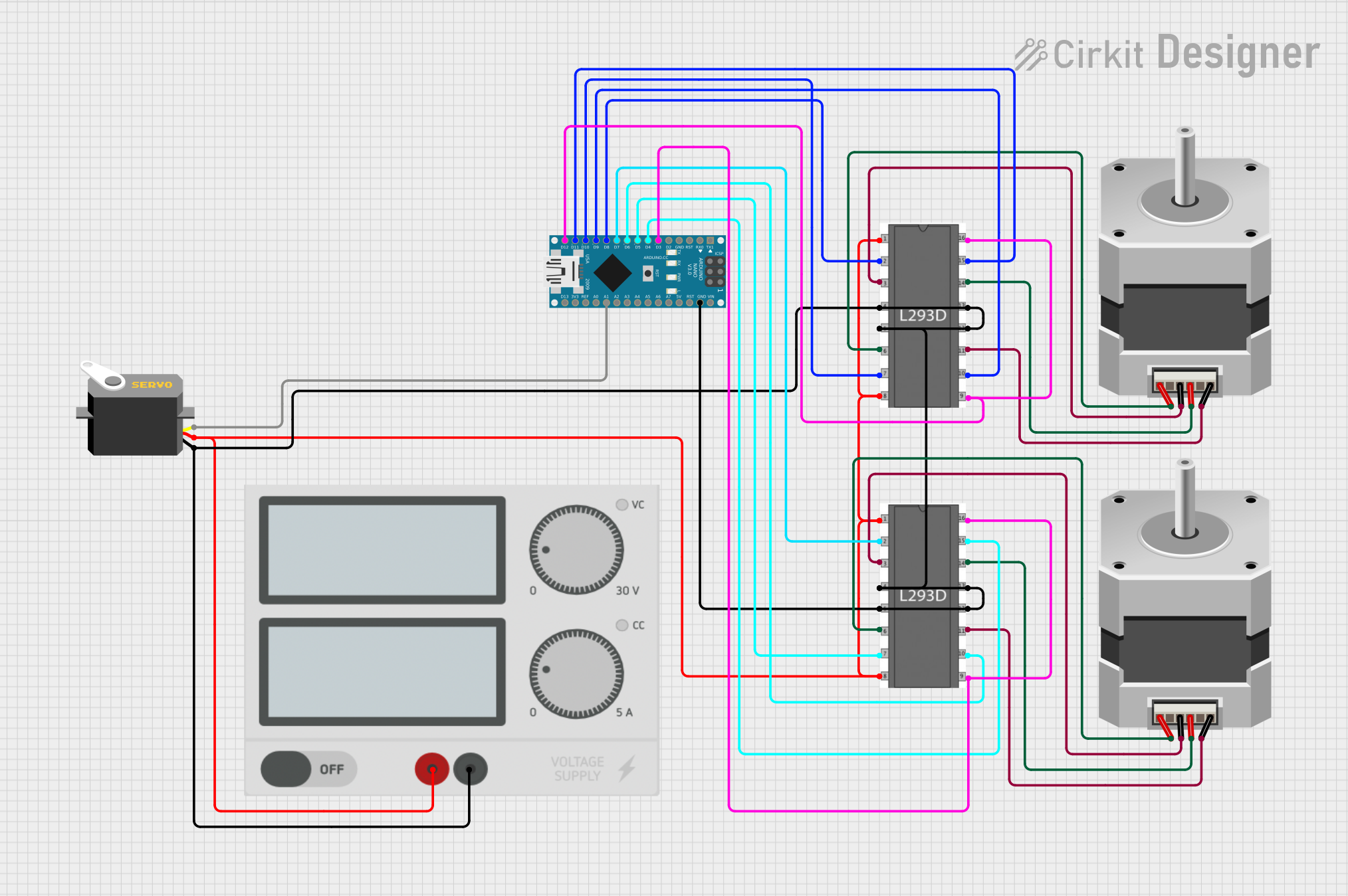
This document provides a detailed overview of a circuit that includes an Arduino Nano microcontroller, two stepper motors, a servo motor, a power supply, and two L293D motor drivers. The Arduino Nano is used to control the motors through the motor drivers, and the servo motor is directly controlled by the Arduino. The power supply provides the necessary voltage to the components.
Component List
Arduino Nano
- Description: A small, complete, and breadboard-friendly board based on the ATmega328P.
- Pins: D1/TX, D0/RX, RESET, GND, D2, D3, D4, D5, D6, D7, D8, D9, D10, D11/MOSI, D12/MISO, VIN, 5V, A7, A6, A5, A4, A3, A2, A1, A0, AREF, 3V3, D13/SCK
Stepper Motor (Bipolar)
- Description: A bipolar stepper motor with four pins.
- Pins: D, B, C, A
Servo
- Description: A servo motor with three pins.
- Pins: gnd, vcc, pulse
Power Supply
- Description: A power supply with two pins.
- Pins: +, -
L293D Motor Driver
- Description: A motor driver IC used to control the stepper motors.
- Pins: enable 1, input 1, output 1, gnd, output 2, input 2, vs, vss, input 4, output 4, output 3, input 3, enable 2
Wiring Details
Arduino Nano
- D3 connected to L293D Motor Driver (enable 2, vss)
- D4 connected to L293D Motor Driver (input 4)
- D5 connected to L293D Motor Driver (input 2)
- D6 connected to L293D Motor Driver (input 3)
- D7 connected to L293D Motor Driver (input 1)
- D8 connected to L293D Motor Driver (input 1)
- D9 connected to L293D Motor Driver (input 3)
- D10 connected to L293D Motor Driver (input 2)
- D11/MOSI connected to L293D Motor Driver (input 4)
- D12/MISO connected to L293D Motor Driver (enable 2, vss)
- GND connected to Power Supply (-), L293D Motor Driver (gnd), Servo (gnd)
- A1 connected to Servo (pulse)
Stepper Motor (Bipolar)
- D connected to L293D Motor Driver (output 3)
- B connected to L293D Motor Driver (output 4)
- C connected to L293D Motor Driver (output 1)
- A connected to L293D Motor Driver (output 2)
Stepper Motor (Bipolar)
- D connected to L293D Motor Driver (output 3)
- B connected to L293D Motor Driver (output 4)
- C connected to L293D Motor Driver (output 1)
- A connected to L293D Motor Driver (output 2)
Servo
- gnd connected to Arduino Nano (GND)
- vcc connected to Power Supply (+)
- pulse connected to Arduino Nano (A1)
Power Supply
- + connected to L293D Motor Driver (enable 1, vs), Servo (vcc)
- - connected to Arduino Nano (GND), L293D Motor Driver (gnd)
L293D Motor Driver
- enable 1 connected to Power Supply (+)
- input 1 connected to Arduino Nano (D7, D8)
- output 1 connected to Stepper Motor (C)
- gnd connected to Power Supply (-), Arduino Nano (GND)
- output 2 connected to Stepper Motor (A)
- input 2 connected to Arduino Nano (D5, D10)
- vs connected to Power Supply (+)
- vss connected to Arduino Nano (D3, D12)
- input 4 connected to Arduino Nano (D4, D11/MOSI)
- output 4 connected to Stepper Motor (B)
- output 3 connected to Stepper Motor (D)
- input 3 connected to Arduino Nano (D6, D9)
- enable 2 connected to Arduino Nano (D3, D12)
Documented Code
Arduino Nano Code (sketch.ino)
void setup() {
  // put your setup code here, to run once:

}

void loop() {
  // put your main code here, to run repeatedly:

}
Documentation (documentation.txt)
This document provides a comprehensive overview of the circuit, including a summary, component list, wiring details, and documented code.