
Arduino-Based Smart Feeding System with RTC, Keypad, LCD, and Servo
View and Edit Project In Cirkit Designer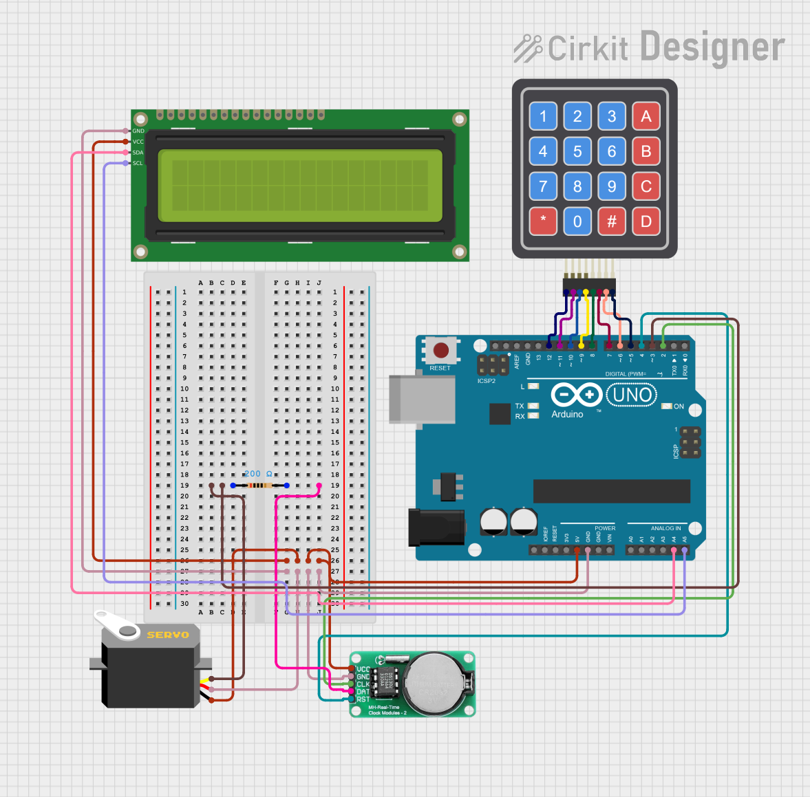
Circuit Documentation
Summary
This circuit is designed to interface an Arduino UNO with a 4x4 Keypad, a 16x2 I2C LCD, a DS1302 RTC module, and a Servo motor. The Arduino UNO serves as the central microcontroller, managing inputs from the keypad, displaying information on the LCD, keeping track of time using the RTC module, and controlling the Servo motor based on specific conditions.
Component List
4x4 Keypad (Simulator)
- Description: A matrix keypad used for user input.
- Pins: R1, C4, R2, C2, R3, R4, C1, C3
16x2 I2C LCD
- Description: A 16x2 character LCD with I2C interface for displaying information.
- Pins: GND, VCC, SDA, SCL
DS1302 RTC
- Description: A Real-Time Clock module for keeping track of time.
- Pins: VCC, GND, CLK, DATA, RST
Arduino UNO
- Description: A microcontroller board based on the ATmega328P.
- Pins: UNUSED, IOREF, Reset, 3.3V, 5V, GND, Vin, A0, A1, A2, A3, A4, A5, SCL, SDA, AREF, D13, D12, D11, D10, D9, D8, D7, D6, D5, D4, D3, D2, D1, D0
Resistor
- Description: A resistor with a resistance of 200 Ohms.
- Pins: pin1, pin2
Servo
- Description: A servo motor for precise control of angular position.
- Pins: gnd, vcc, pulse
Wiring Details
4x4 Keypad (Simulator)
- R1: Connected to Arduino UNO pin D12
- R2: Connected to Arduino UNO pin D11
- R3: Connected to Arduino UNO pin D10
- R4: Connected to Arduino UNO pin D9
- C1: Connected to Arduino UNO pin D8
- C2: Connected to Arduino UNO pin D7
- C3: Connected to Arduino UNO pin D6
- C4: Connected to Arduino UNO pin D5
16x2 I2C LCD
- GND: Connected to Arduino UNO GND
- VCC: Connected to Arduino UNO 5V
- SDA: Connected to Arduino UNO pin A4
- SCL: Connected to Arduino UNO pin A5
DS1302 RTC
- VCC: Connected to Arduino UNO 5V
- GND: Connected to Arduino UNO GND
- CLK: Connected to Arduino UNO pin D2
- DATA: Connected to Resistor pin2
- RST: Connected to Arduino UNO pin D4
Arduino UNO
- D3: Connected to Resistor pin1
- 5V: Connected to Servo gnd, 16x2 I2C LCD VCC, DS1302 RTC VCC
- GND: Connected to Servo vcc, 16x2 I2C LCD GND, DS1302 RTC GND
- A4: Connected to 16x2 I2C LCD SDA
- A5: Connected to 16x2 I2C LCD SCL
- D12: Connected to 4x4 Keypad R1
- D11: Connected to 4x4 Keypad R2
- D10: Connected to 4x4 Keypad R3
- D9: Connected to 4x4 Keypad R4
- D8: Connected to 4x4 Keypad C1
- D7: Connected to 4x4 Keypad C2
- D6: Connected to 4x4 Keypad C3
- D5: Connected to 4x4 Keypad C4
- D4: Connected to DS1302 RTC RST
- D2: Connected to DS1302 RTC CLK
Resistor
- pin1: Connected to Arduino UNO pin D3
- pin2: Connected to DS1302 RTC DATA
Servo
- gnd: Connected to Arduino UNO 5V
- vcc: Connected to Arduino UNO GND
- pulse: Connected to Arduino UNO pin D3
Documented Code
#include <Keypad.h>
#include <virtuabotixRTC.h>
#include <LiquidCrystal_I2C.h>
#include <Servo.h>

#define I2C_ADDR 0x27

LiquidCrystal_I2C lcd(I2C_ADDR, 20, 4);
virtuabotixRTC myRTC(2, 3, 4);  // CLK, DAT, RST
Servo myServo;
int pos = 0;

const byte numRows = 4;
const byte numCols = 4;

char keymap[numRows][numCols] = {
    {'1', '2', '3', 'A'},
    {'4', '5', '6', 'B'},
    {'7', '8', '9', 'C'},
    {'*', '0', '#', 'D'}};

byte rowPins[numRows] = {12, 11, 10, 9};
byte colPins[numCols] = {8, 7, 6, 5};

Keypad myKeypad = Keypad(makeKeymap(keymap), rowPins, colPins, numRows, numCols);

int alarmHour = -1, alarmMinute = -1;
bool alarmSet = false;
bool alarmTriggered = false;

int alarm2Hour = -1, alarm2Minute = -1;
bool alarm2Set = false;
bool alarm2Triggered = false;

bool setupMode = false;
bool programActive = true;

void setup() {
  Serial.begin(9600);
  lcd.init();
  lcd.backlight();
  lcd.setCursor(0, 0);
  lcd.print("Initializing...");
  delay(2000);

  myRTC.setDS1302Time(0, 0, 12, 1, 23, 11, 2024);
  lcd.setCursor(0, 1);
  lcd.print("RTC Ready");
  delay(2000);

  myServo.attach(3);
  myServo.write(0);
}

void loop() {
  char keypressed = myKeypad.getKey();

  if (keypressed == '*') {
    programActive = !programActive;
    lcd.clear();
    if (programActive) {
      lcd.backlight();
      lcd.print("Program ON");
    } else {
      lcd.noBacklight();
      lcd.clear();
    }
    delay(1000);
  }

  if (!programActive) {
    return;
  }

  lcd.clear();
  myRTC.updateTime();
  displayTime();
  delay(1000);

  if (keypressed == '#') {
    enterSetupMode();
  } else if (keypressed == 'A') {
    enterAlarmSetupMode(1);
  } else if (keypressed == 'B') {
    enterAlarmSetupMode(2);
  }

  if (alarmSet && checkAlarm(alarmHour, alarmMinute, alarmTriggered)) {
    triggerAlarm(1);
  }
  if (alarm2Set && checkAlarm(alarm2Hour, alarm2Minute, alarm2Triggered)) {
    triggerAlarm(2);
  }
}

void displayTime() {
  lcd.setCursor(0, 0);
  lcd.print(myRTC.dayofmonth);
  lcd.print("/");
  lcd.print(myRTC.month);
  lcd.print("/");
  lcd.print(myRTC.year);

  lcd.setCursor(0, 1);
  lcd.print(myRTC.hours);
  lcd.print(":");
  lcd.print(myRTC.minutes);
  lcd.print(":");
  lcd.print(myRTC.seconds);
}

void enterSetupMode() {
  setupMode = true;
  lcd.clear();
  lcd.print("Setup Mode...");
  delay(500);
  setupRTC();
  setupMode = false;
}

void enterAlarmSetupMode(int alarmNumber) {
  setupMode = true;
  lcd.clear();
  lcd.print(alarmNumber == 1 ? "Set Feeding 1:" : "Set Feeding 2:");
  delay(500);
  setupAlarm(alarmNumber);
  lcd.clear();
  setupMode = false;
}

void setupRTC() {
  int year, month, day, hour, minute;

  lcd.clear();
  lcd.print("Setup Year:");
  year = getInput(4);

  lcd.clear();
  lcd.print("Setup Month:");
  month = getInput(2);

  lcd.clear();
  lcd.print("Setup Day:");
  day = getInput(2);

  lcd.clear();
  lcd.print("Setup Hour:");
  hour = getInput(2);

  lcd.clear();
  lcd.print("Setup Minute:");
  minute = getInput(2);