
Arduino UNO-Based Smart Sensor Hub with RFID and Load Cell Integration
View and Edit Project In Cirkit Designer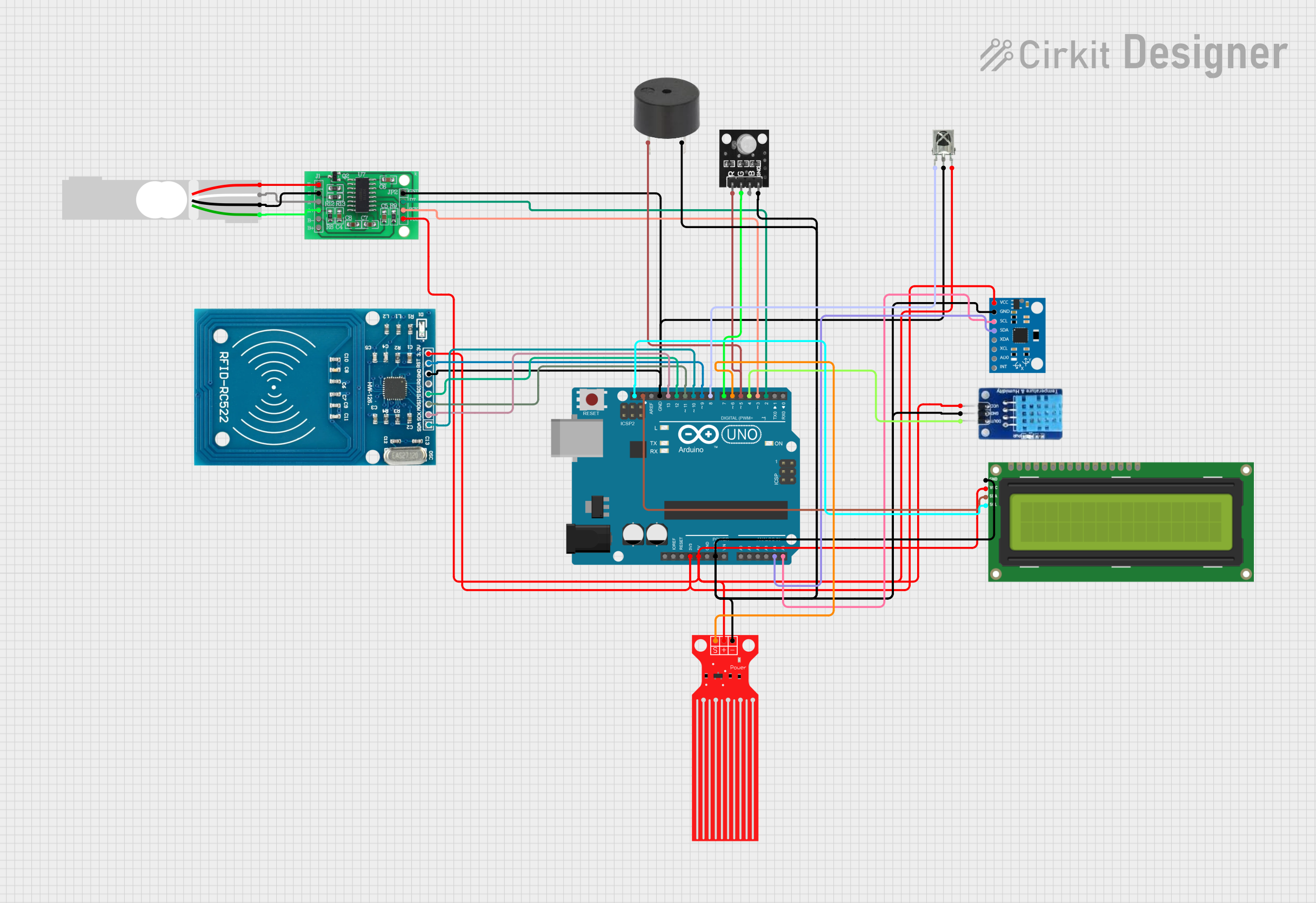
Circuit Documentation
Summary
This document provides a detailed overview of a circuit that integrates various sensors, an RFID module, an LCD screen, and other components with an Arduino UNO microcontroller. The circuit is designed to interface with multiple peripherals to perform various sensing and control tasks.
Component List
Arduino UNO
- Description: A microcontroller board based on the ATmega328P.
- Pins: UNUSED, IOREF, Reset, 3.3V, 5V, GND, Vin, A0, A1, A2, A3, A4, A5, SCL, SDA, AREF, D13, D12, D11, D10, D9, D8, D7, D6, D5, D4, D3, D2, D1, D0
Load Cell - Red/white/black/green
- Description: A sensor used to measure weight or force.
- Pins: E+, A-, E-, A+
HX711 - Bridge Sensor Interface
- Description: An ADC for weigh scales.
- Pins: E+, E-, A-, A+, B-, B+, GND - GROUND, DATA (OUT), SCK - CLOCK (IN), 3.3/3.5V Supply
RFID-RC522
- Description: An RFID reader module.
- Pins: VCC (3.3V), RST, GND, IRQ, MISO, MOSI, SCK, SDA
RGB Led module
- Description: An RGB LED module for visual indications.
- Pins: +VCC Red, +VCC Green, +VCC Blue, GND
Buzzer
- Description: An audio signaling device.
- Pins: PIN, GND
MPU6050
- Description: A 6-axis motion tracking device.
- Pins: vcc, gnd, scl, sda, xda, xcl, AD0, int, 3.3v
DHT11
- Description: A temperature and humidity sensor.
- Pins: DATA, GND, VCC
I2C LCD 16x2 Screen
- Description: A 16x2 character LCD with I2C interface.
- Pins: SCL, SDA, VCC (5V), GND, VDD, VO, RS, RW, E, D0, D1, D2, D3, D4, D5, D6, D7, BLA, BLK
Water Level Sensor
- Description: A sensor to measure water level.
- Pins: SIG, VCC, GND
VS1838B IR Receiver
- Description: An IR receiver module.
- Pins: OUT, GND, VCC
Wiring Details
Arduino UNO
- 3.3V: Connected to VCC (3.3V) of RFID-RC522, vcc of MPU6050
- 5V: Connected to VCC (5V) of I2C LCD 16x2 Screen, VCC of Water Level Sensor, 3.3/3.5V Supply of HX711, VCC of VS1838B IR Receiver, VCC of DHT11
- GND: Connected to GND of I2C LCD 16x2 Screen, GND of Water Level Sensor, gnd of MPU6050, GND of buzzer, GND of RGB Led module, GND of DHT11, GND of RFID-RC522, GND - GROUND of HX711, GND of VS1838B IR Receiver
- A4: Connected to sda of MPU6050
- A5: Connected to scl of MPU6050
- SCL: Connected to SCL of I2C LCD 16x2 Screen
- SDA: Connected to SDA of I2C LCD 16x2 Screen
- D13: Connected to SCK of RFID-RC522
- D12: Connected to MISO of RFID-RC522
- D11: Connected to MOSI of RFID-RC522
- D10: Connected to SDA of RFID-RC522
- D9: Connected to RST of RFID-RC522
- D8: Connected to OUT of VS1838B IR Receiver
- D7: Connected to +VCC Green of RGB Led module
- D6: Connected to SIG of Water Level Sensor
- D5: Connected to PIN of buzzer, +VCC Red of RGB Led module
- D4: Connected to DATA of DHT11
- D3: Connected to SCK - CLOCK (IN) of HX711
- D2: Connected to DATA (OUT) of HX711
Load Cell - Red/white/black/green
- E+: Connected to E+ of HX711
- A-: Connected to A- of HX711
- E-: Connected to E- of HX711
- A+: Connected to A+ of HX711
HX711 - Bridge Sensor Interface
- E+: Connected to E+ of Load Cell
- A-: Connected to A- of Load Cell
- E-: Connected to E- of Load Cell
- A+: Connected to A+ of Load Cell
- GND - GROUND: Connected to GND of Arduino UNO
- DATA (OUT): Connected to D2 of Arduino UNO
- SCK - CLOCK (IN): Connected to D3 of Arduino UNO
- 3.3/3.5V Supply: Connected to 5V of Arduino UNO
RFID-RC522
- VCC (3.3V): Connected to 3.3V of Arduino UNO
- RST: Connected to D9 of Arduino UNO
- GND: Connected to GND of Arduino UNO
- SCK: Connected to D13 of Arduino UNO
- MISO: Connected to D12 of Arduino UNO
- MOSI: Connected to D11 of Arduino UNO
- SDA: Connected to D10 of Arduino UNO
RGB Led module
- +VCC Red: Connected to D5 of Arduino UNO
- +VCC Green: Connected to D7 of Arduino UNO
- +VCC Blue: Not connected
- GND: Connected to GND of Arduino UNO
Buzzer
- PIN: Connected to D5 of Arduino UNO
- GND: Connected to GND of Arduino UNO
MPU6050
- vcc: Connected to 3.3V of Arduino UNO
- gnd: Connected to GND of Arduino UNO
- scl: Connected to A5 of Arduino UNO
- sda: Connected to A4 of Arduino UNO
DHT11
- DATA: Connected to D4 of Arduino UNO
- GND: Connected to GND of Arduino UNO
- VCC: Connected to 5V of Arduino UNO
I2C LCD 16x2 Screen
- SCL: Connected to SCL of Arduino UNO
- SDA: Connected to SDA of Arduino UNO
- VCC (5V): Connected to 5V of Arduino UNO
- GND: Connected to GND of Arduino UNO
Water Level Sensor
- SIG: Connected to D6 of Arduino UNO
- VCC: Connected to 5V of Arduino UNO
- GND: Connected to GND of Arduino UNO
VS1838B IR Receiver
- OUT: Connected to D8 of Arduino UNO
- GND: Connected to GND of Arduino UNO
- VCC: Connected to 5V of Arduino UNO
Code Documentation
Arduino UNO Code
void setup() {
  // put your setup code here, to run once:

}

void loop() {
  // put your main code here, to run repeatedly:

}
This code is a basic template for the Arduino UNO. The setup() function is where you initialize your components and settings, and the loop() function is where the main logic of your program runs repeatedly.
This document provides a comprehensive overview of the circuit, including the components used, their wiring details, and the initial code setup for the Arduino UNO.