Cirkit Designer
Your all-in-one circuit design IDE
Home /
Project Documentation
6V DC Motor Control Circuit
Circuit Documentation
Summary of the Circuit
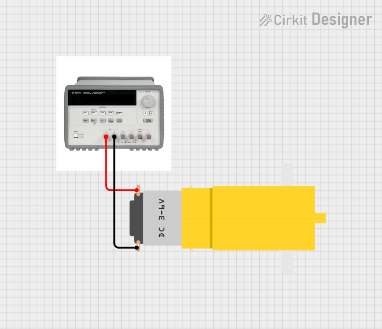
The circuit described by the provided inputs consists of a simple power supply and motor setup. The circuit uses a triple output DC power supply to provide the necessary voltage and current to drive a yellow hobby gear motor. The power supply is configured to deliver a 6V output to the motor. There is no microcontroller or embedded code involved in this circuit, indicating that the motor runs directly off the power supply without any control logic.
Component List
Triple Output DC Power Supply
- Description: A power supply capable of providing multiple voltage outputs. In this circuit, only the 6V output is used.
- Pins:
- 6V +
- 6V -
- GND
- 25V +
- 25V COM
- 25V -
Motor Amarillo Motorreductor Hobby
- Description: A yellow hobby gear motor that operates on a voltage provided by the power supply.
- Pins:
- VCC
- GND
Wiring Details
Triple Output DC Power Supply
- 6V + is connected to the VCC pin of the Motor Amarillo Motorreductor Hobby.
- 6V - is connected to the GND pin of the Motor Amarillo Motorreductor Hobby.
- The other pins (GND, 25V +, 25V COM, 25V -) are not used in this circuit.
Motor Amarillo Motorreductor Hobby
- VCC is connected to the 6V + pin of the Triple Output DC Power Supply.
- GND is connected to the 6V - pin of the Triple Output DC Power Supply.
Documented Code
There is no embedded code provided for this circuit as there are no microcontroller components involved. The motor operation is directly controlled by the power supply without any programmable interface.