
Arduino UNO Based RS-485 Communication System with Pushbutton Activation and LED Indicator
View and Edit Project In Cirkit Designer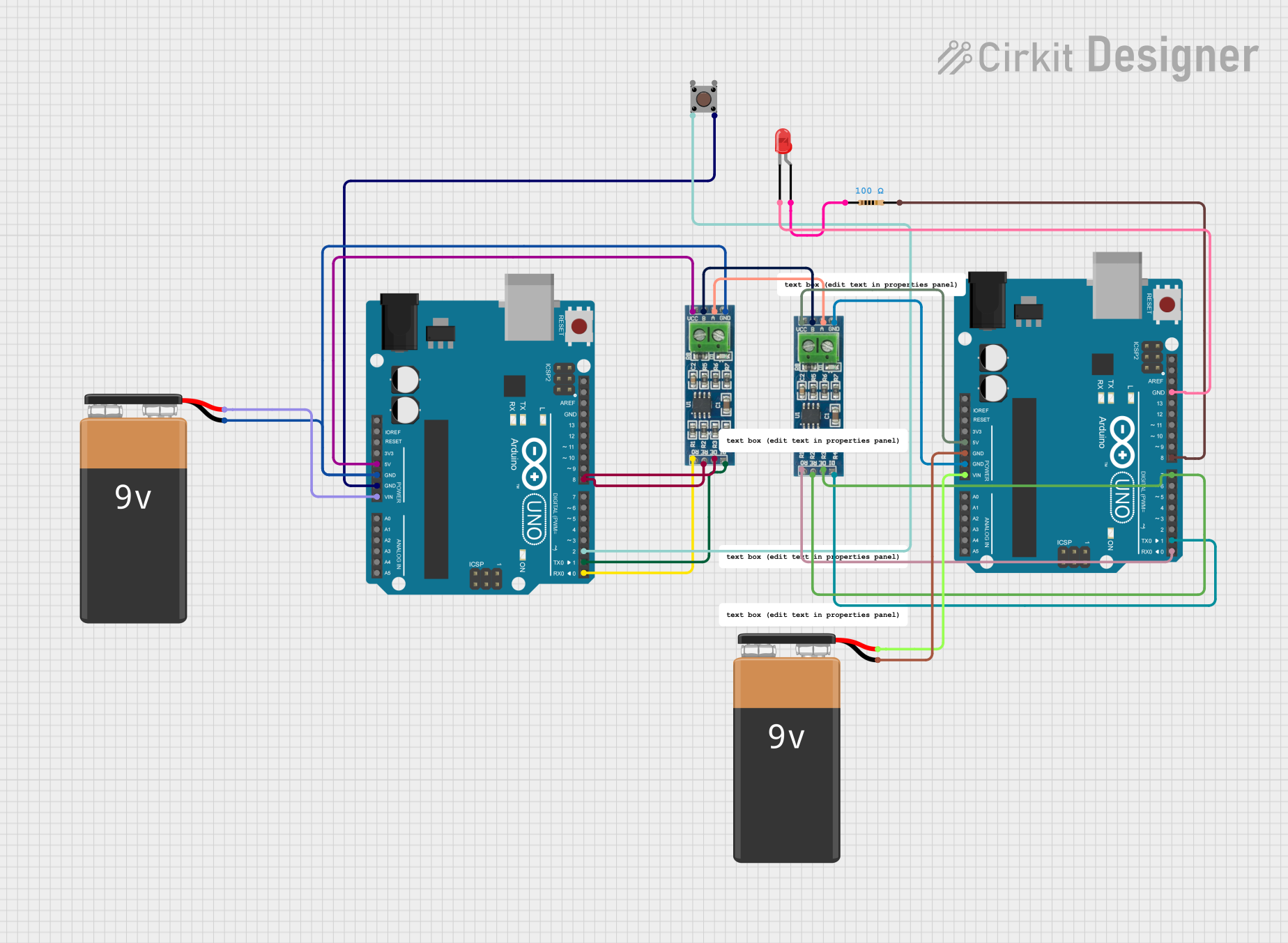
Circuit Documentation
Summary
The circuit in question is designed to demonstrate a communication system using two RS-485 modules interfaced with two Arduino UNO microcontrollers. The RS-485 standard allows for robust serial communication over long distances and in electrically noisy environments. One Arduino acts as a master, sending a message when a pushbutton is pressed, while the other Arduino acts as a slave, receiving the message and responding by lighting up an LED. The system is powered by two separate 9V batteries.
Component List
Microcontrollers
- Arduino UNO (Master): A microcontroller board based on the ATmega328P, with digital and analog I/O pins.
- Arduino UNO (Slave): Another instance of the Arduino UNO board, used to receive messages from the master.
Communication Modules
- RS-485 Module (Master): An interface module for RS-485 communication, connected to the master Arduino.
- RS-485 Module (Slave): An identical interface module for RS-485 communication, connected to the slave Arduino.
Power Sources
- 9V Battery (Master): Provides power to the master Arduino UNO.
- 9V Battery (Slave): Provides power to the slave Arduino UNO.
Indicators and Interfaces
- LED (Red): A simple red LED used to indicate the reception of a message by the slave Arduino.
- Pushbutton: A button that, when pressed, triggers the master Arduino to send a message.
Passive Components
- Resistor (100 Ohms): Limits the current through the LED to prevent damage.
Comments
- Comment: Non-electrical components used for annotations in the circuit design.
Wiring Details
Arduino UNO (Master)
- 5V connected to RS-485 Module (Master) VCC.
- GND connected to RS-485 Module (Master) GND and 9V Battery (Master) negative terminal.
- D0 (RX) connected to RS-485 Module (Master) RO.
- D7 connected to RS-485 Module (Master) RE and DE.
- D1 (TX) connected to RS-485 Module (Master) DI.
- Vin connected to 9V Battery (Master) positive terminal.
Arduino UNO (Slave)
- 5V connected to RS-485 Module (Slave) VCC.
- GND connected to RS-485 Module (Slave) GND, Pushbutton Pin 4 (out), and 9V Battery (Slave) negative terminal.
- D0 (RX) connected to RS-485 Module (Slave) RO.
- D8 connected to RS-485 Module (Slave) RE and DE, and through a 100 Ohm Resistor to LED anode.
- D1 (TX) connected to RS-485 Module (Slave) DI.
- D2 connected to Pushbutton Pin 2 (in).
- Vin connected to 9V Battery (Slave) positive terminal.
RS-485 Module (Master)
- VCC connected to Arduino UNO (Master) 5V.
- B connected to RS-485 Module (Slave) B.
- A connected to RS-485 Module (Slave) A.
- GND connected to Arduino UNO (Master) GND.
- RO connected to Arduino UNO (Master) D0 (RX).
- RE connected to Arduino UNO (Master) D7.
- DE connected to Arduino UNO (Master) D7.
- DI connected to Arduino UNO (Master) D1 (TX).
RS-485 Module (Slave)
- VCC connected to Arduino UNO (Slave) 5V.
- B connected to RS-485 Module (Master) B.
- A connected to RS-485 Module (Master) A.
- GND connected to Arduino UNO (Slave) GND and 9V Battery (Slave) negative terminal.
- RO connected to Arduino UNO (Slave) D0 (RX).
- RE connected to Arduino UNO (Slave) D8.
- DE connected to Arduino UNO (Slave) D8.
- DI connected to Arduino UNO (Slave) D1 (TX).
LED (Red)
- Cathode connected to Arduino UNO (Slave) GND.
- Anode connected through a 100 Ohm Resistor to Arduino UNO (Slave) D8.
Pushbutton
- Pin 4 (out) connected to Arduino UNO (Slave) GND.
- Pin 2 (in) connected to Arduino UNO (Slave) D2.
Resistor (100 Ohms)
- Pin1 connected to LED (Red) anode.
- Pin2 connected to Arduino UNO (Slave) D8.
Documented Code
Arduino UNO (Master) Code
#define MASTER_EN 8
#define SWITCH 2
void setup() {
  // put your setup code here, to run once:
  pinMode (SWITCH , INPUT_PULLUP) ;
  pinMode (MASTER_EN , OUTPUT) ;
  Serial.begin (9600);
  digitalWrite (MASTER_EN , LOW) ;
}

void loop() {
  // put your main code here, to run repeatedly:
  if (digitalRead (SWITCH) == 0)
  {
    delay (1000);
    digitalWrite (MASTER_EN , HIGH) ;
    delay (5);
    Serial.print ("EMBEDDED GATE*") ;
    Serial.flush ();
    digitalWrite (MASTER_EN , LOW) ;
  }
}
This code configures the master Arduino to send a message "EMBEDDED GATE*" over the RS-485 module when the pushbutton is pressed.
Arduino UNO (Slave) Code
#define SLAVE_EN 7
#define LED 8
String recInput;
void setup() {
  // put your setup code here, to run once:
  pinMode (LED , OUTPUT) ;
  pinMode (SLAVE_EN , OUTPUT) ;
  Serial.begin (9600);
  digitalWrite (SLAVE_EN , LOW) ;
}

void loop() {
  // put your main code here, to run repeatedly:
  while (Serial.available())
  {
    recInput = Serial.readStringUntil('*');
    Serial.print(recInput);
    if (recInput == "EMBEDDED GATE")
    {
      digitalWrite(LED, HIGH);
      delay(1000);
      digitalWrite(LED, LOW);
    }
  }
}
This code configures the slave Arduino to listen for the message "EMBEDDED GATE*" from the master. Upon receiving the message, it turns on the LED for 1 second.
(Note: The code for the 9V Battery microcontroller instances is empty and thus not included in the documentation.)