
Arduino-Based Smart Shopping Trolley with RFID and LCD Display
View and Edit Project In Cirkit Designer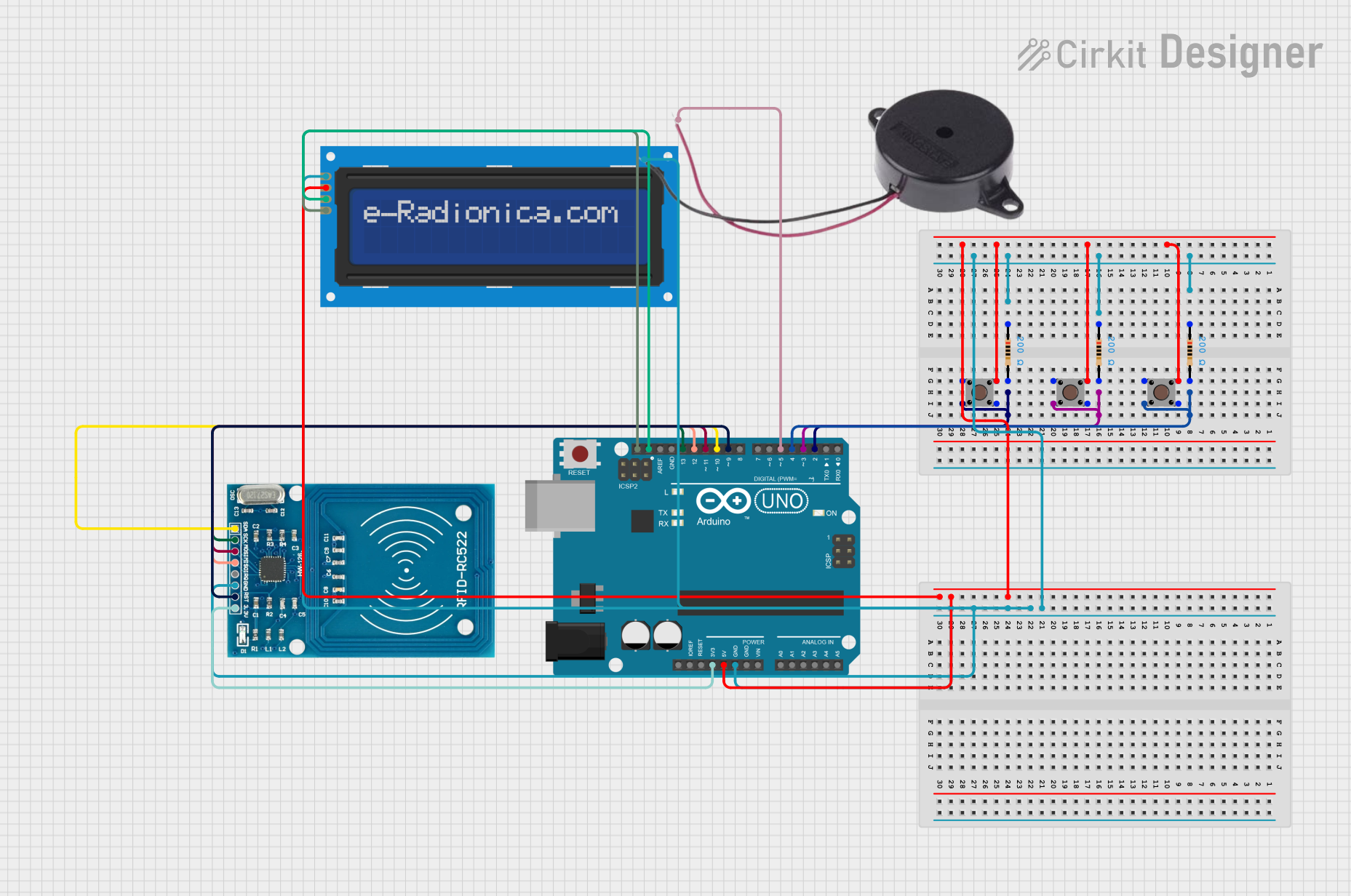
Circuit Documentation
Summary
The circuit in question is designed to interface an Arduino UNO with multiple peripherals including pushbuttons, resistors, an LCD screen with I2C interface, a buzzer, and an RFID-RC522 module. The circuit appears to be part of a smart trolley billing system, where the pushbuttons are used to add or remove items from the bill, the RFID reader scans items, the buzzer provides audio feedback, and the LCD displays billing information.
Component List
Pushbutton
- Description: A standard pushbutton used for user input.
- Pins: Pin 3 (out), Pin 4 (out), Pin 1 (in), Pin 2 (in).
Resistor (200 Ohms)
- Description: A resistor with a resistance of 200 Ohms, likely used for current limiting or pull-up/pull-down purposes.
- Pins: pin1, pin2.
Arduino UNO
- Description: A microcontroller board based on the ATmega328P, used as the main controller for the circuit.
- Pins: UNUSED, IOREF, Reset, 3.3V, 5V, GND, Vin, A0-A5, SCL, SDA, AREF, D0-D13.
LCD screen 16x2 I2C
- Description: A 16x2 character LCD display with an I2C interface for displaying text.
- Pins: SCL, SDA, VCC, GND.
Buzzer
- Description: An electronic buzzer for audible alerts.
- Pins: POSITIVE, NEGATIVE.
RFID-RC522
- Description: An RFID reader/writer module for contactless communication using radio frequency.
- Pins: VCC (3.3V), RST, GND, IRQ, MISO, MOSI, SCK, SDA.
Wiring Details
Pushbutton
- Pin 4 (out): Connected to the corresponding input pin on the Arduino UNO.
- Pin 2 (in): Connected to the ground through a resistor.
- Pin 3 (out): Connected to 5V on the Arduino UNO.
- Pin 1 (in): Connected to the ground through a resistor.
Resistor (200 Ohms)
- pin1: Connected to the ground net, shared with the buzzer NEGATIVE pin, LCD GND pin, RFID GND pin, and Arduino GND pin.
- pin2: Connected to the corresponding pushbutton Pin 2 (in) or Pin 4 (out).
Arduino UNO
- 3.3V: Powers the RFID-RC522 module.
- 5V: Powers the LCD screen.
- GND: Common ground for the circuit.
- D2, D3, D4: Connected to pushbuttons for input detection.
- D5: Connected to the buzzer POSITIVE pin.
- D9-D13: Connected to the RFID-RC522 module for SPI communication.
- SCL, SDA: Connected to the LCD screen for I2C communication.
LCD screen 16x2 I2C
- SCL: Connected to the Arduino SCL pin.
- SDA: Connected to the Arduino SDA pin.
- VCC: Powered by 5V from the Arduino UNO.
- GND: Connected to the common ground net.
Buzzer
- POSITIVE: Connected to the D5 pin on the Arduino UNO.
- NEGATIVE: Connected to the common ground net.
RFID-RC522
- VCC (3.3V): Powered by 3.3V from the Arduino UNO.
- RST: Connected to the D9 pin on the Arduino UNO.
- GND: Connected to the common ground net.
- MISO, MOSI, SCK, SDA: Connected to the corresponding SPI pins on the Arduino UNO.
Documented Code
The code provided is for the Arduino UNO microcontroller and is designed to operate the smart trolley billing system. It includes the initialization and operation of the RFID-RC522 module, the LCD screen, and the buzzer. It also handles the input from the pushbuttons to add or remove items from the bill and to reset the system.
/****************************************************
 * Code Designed By : Rahul Jadhav Youtube Channel
 ****************************************************/

/******************RFID Connection:*********************

RFID PIN    ARDUINO PIN
SDA         10
SCK         13
MOSI        11
MISO        12
GND         GND
RST         9
3.3v        3.3v
 ******************************************************/

/***** LCD Connection ***********************************
LCD PIN   ARDUINO PI
SCL       SCL (Arduino Last pin)
SDA       SDA (Arduino Secon last pin)
VCC       5v
GND       GND
 ******************************************************/

/***** Buzzer Connection ***********************************
Buzzer PIN   ARDUINO PI
Positive     5
GND          GND
 *****************************************************/

/***** Button Connection ***********************************
Button PIN   ARDUINO PI
Remove_Button     2
Add_button         3
Reset_button       4
VCC          5v
GND          GND
 *****************************************************/

#include <SPI.h>
#include <MFRC522.h>
#include <LiquidCrystal_I2C.h>

LiquidCrystal_I2C lcd(0x27, 16, 2);
const int remove_button = 2;
const int add_button = 3;
const int reset_button = 4;
const int buzzer_Pin = 5;
#define SS_PIN 10
#define RST_PIN 9
MFRC522 mfrc522(SS_PIN, RST_PIN);   // Create MFRC522 instance.

// Rest of the code is omitted for brevity
The code initializes the LCD and RFID reader, sets up the button pins, and enters a loop where it waits for button presses or RFID card detection. When a card is detected, it checks if the item should be added or removed from the bill and updates the LCD and buzzer accordingly.