Arduino UNO Controlled LED Array with Pushbutton Inputs
Circuit Documentation
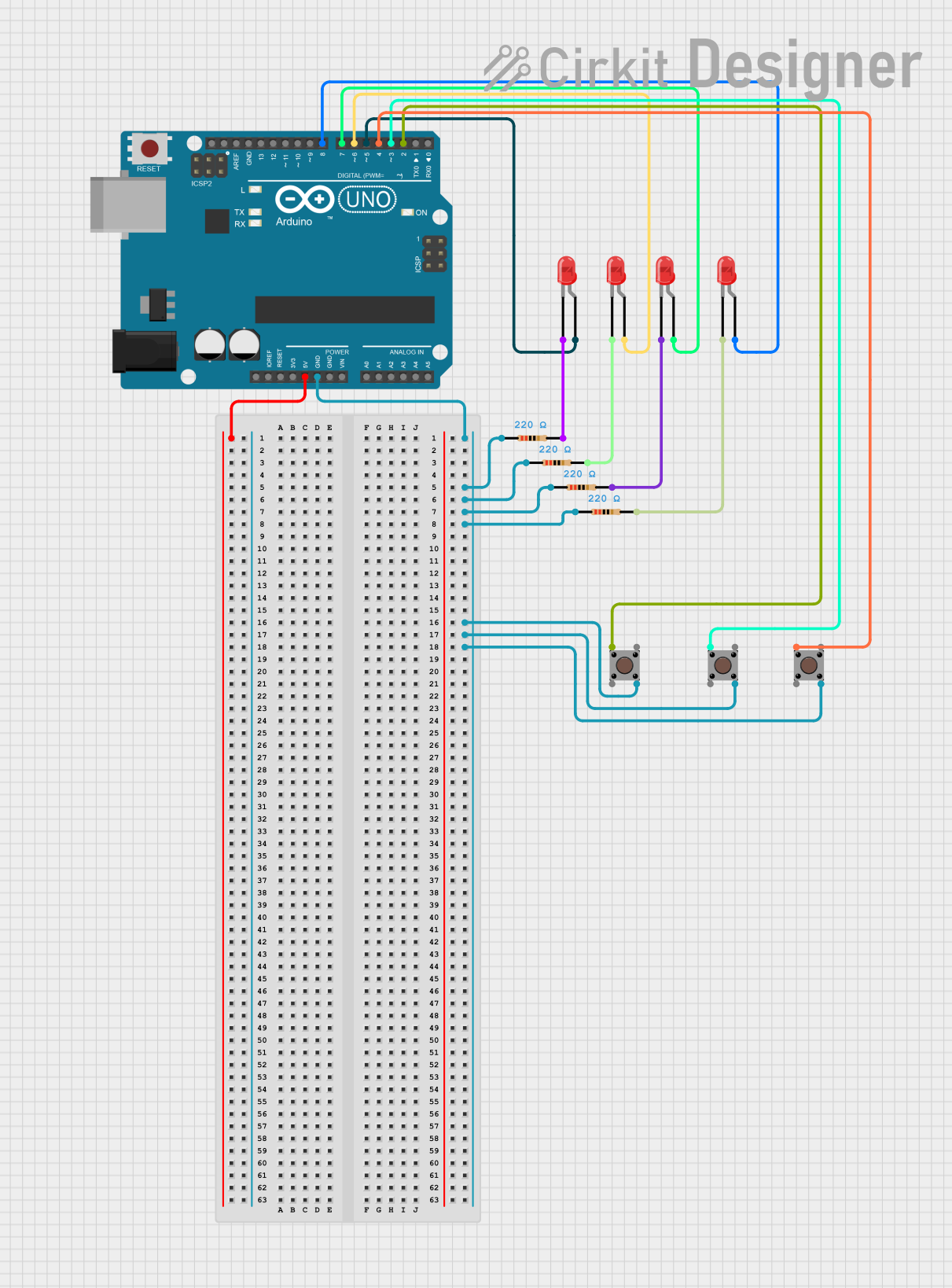
Summary
This circuit is designed to control four LEDs using an Arduino UNO microcontroller. The LEDs are controlled via serial commands sent from MobiFlight. Each LED can be turned on or off based on specific commands received by the Arduino. Additionally, the circuit includes pushbuttons and resistors to manage the LED states and ensure proper current flow.
Component List
Arduino UNO
- Description: Microcontroller board based on the ATmega328P.
- Pins: UNUSED, IOREF, Reset, 3.3V, 5V, GND, Vin, A0, A1, A2, A3, A4, A5, SCL, SDA, AREF, D13, D12, D11, D10, D9, D8, D7, D6, D5, D4, D3, D2, D1, D0
Resistor (220 Ohms)
- Description: Resistor with a resistance of 220 Ohms.
- Pins: pin1, pin2
LED: Two Pin (red)
- Description: Red LED with two pins.
- Pins: cathode, anode
Pushbutton
- Description: Pushbutton switch.
- Pins: Pin 3 (out), Pin 4 (out), Pin 1 (in), Pin 2 (in)
Wiring Details
Arduino UNO
5V: Connected to the power supply.
GND: Connected to:
- pin1 of Resistor 1
- pin1 of Resistor 2
- pin1 of Resistor 3
- pin1 of Resistor 4
- Pin 4 (out) of Pushbutton 1
- Pin 4 (out) of Pushbutton 2
- Pin 4 (out) of Pushbutton 3
D8: Connected to the anode of LED 4.
D7: Connected to the anode of LED 3.
D6: Connected to the anode of LED 2.
D5: Connected to the anode of LED 1.
D4: Connected to Pin 1 (in) of Pushbutton 3.
D3: Connected to Pin 1 (in) of Pushbutton 2.
D2: Connected to Pin 1 (in) of Pushbutton 1.
Resistor 1 (220 Ohms)
- pin1: Connected to GND.
- pin2: Connected to the cathode of LED 1.
Resistor 2 (220 Ohms)
- pin1: Connected to GND.
- pin2: Connected to the cathode of LED 2.
Resistor 3 (220 Ohms)
- pin1: Connected to GND.
- pin2: Connected to the cathode of LED 3.
Resistor 4 (220 Ohms)
- pin1: Connected to GND.
- pin2: Connected to the cathode of LED 4.
LED 1 (Red)
- anode: Connected to D5 of Arduino UNO.
- cathode: Connected to pin2 of Resistor 1.
LED 2 (Red)
- anode: Connected to D6 of Arduino UNO.
- cathode: Connected to pin2 of Resistor 2.
LED 3 (Red)
- anode: Connected to D7 of Arduino UNO.
- cathode: Connected to pin2 of Resistor 3.
LED 4 (Red)
- anode: Connected to D8 of Arduino UNO.
- cathode: Connected to pin2 of Resistor 4.
Pushbutton 1
- Pin 1 (in): Connected to D2 of Arduino UNO.
- Pin 4 (out): Connected to GND.
Pushbutton 2
- Pin 1 (in): Connected to D3 of Arduino UNO.
- Pin 4 (out): Connected to GND.
Pushbutton 3
- Pin 1 (in): Connected to D4 of Arduino UNO.
- Pin 4 (out): Connected to GND.
Code Documentation
// Define pin numbers for LEDs
const int ledPin1 = 5;
const int ledPin2 = 6;
const int ledPin3 = 7;
const int ledPin4 = 8;

void setup() {
  // Initialize the LED pins as output
  pinMode(ledPin1, OUTPUT);
  pinMode(ledPin2, OUTPUT);
  pinMode(ledPin3, OUTPUT);
  pinMode(ledPin4, OUTPUT);

  // Start serial communication at 9600 baud rate
  Serial.begin(9600);
}

void loop() {
  // Check if data is available to read from the serial port
  if (Serial.available() > 0) {
    // Read the incoming byte
    char command = Serial.read();

    // Control the LEDs based on the received command
    switch (command) {
      case 'A': // Turn on LED 1
        digitalWrite(ledPin1, HIGH);
        break;
      case 'a': // Turn off LED 1
        digitalWrite(ledPin1, LOW);
        break;
      case 'B': // Turn on LED 2
        digitalWrite(ledPin2, HIGH);
        break;
      case 'b': // Turn off LED 2
        digitalWrite(ledPin2, LOW);
        break;
      case 'C': // Turn on LED 3
        digitalWrite(ledPin3, HIGH);
        break;
      case 'c': // Turn off LED 3
        digitalWrite(ledPin3, LOW);
        break;
      case 'D': // Turn on LED 4
        digitalWrite(ledPin4, HIGH);
        break;
      case 'd': // Turn off LED 4
        digitalWrite(ledPin4, LOW);
        break;
      default:
        // Do nothing if an unknown command is received
        break;
    }
  }
}
Code Explanation
- Pin Definitions: The pins for the four LEDs are defined as
ledPin1,ledPin2,ledPin3, andledPin4. - Setup Function: Initializes the LED pins as output and starts serial communication at a baud rate of 9600.
- Loop Function: Continuously checks for incoming serial data. When a command is received, it controls the LEDs based on the command:
- 'A' turns on LED 1, 'a' turns off LED 1.
- 'B' turns on LED 2, 'b' turns off LED 2.
- 'C' turns on LED 3, 'c' turns off LED 3.
- 'D' turns on LED 4, 'd' turns off LED 4.
This setup allows you to control the LEDs via MobiFlight inputs by sending specific commands to the Arduino.