
Battery-Powered Wi-Fi Controlled Sensor and Display System with ESP8266 and MPU-6050
View and Edit Project In Cirkit Designer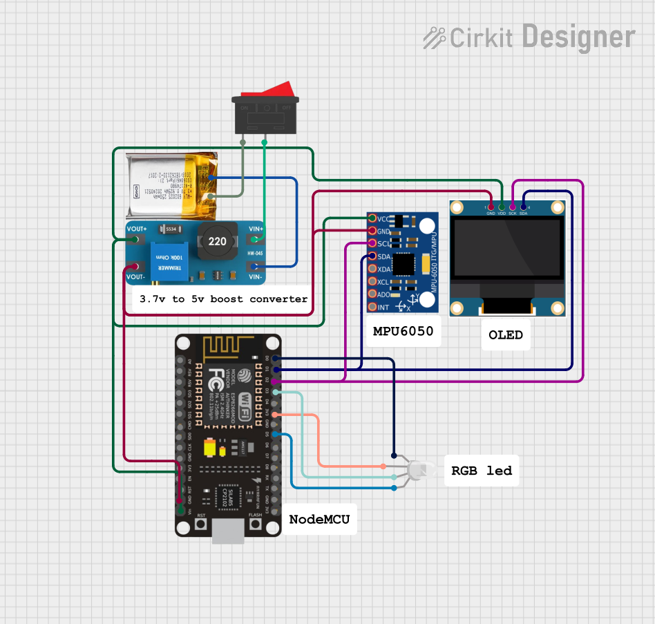
Circuit Documentation
Summary
This document provides a detailed overview of a circuit that includes an ESP8266 NodeMCU, an MPU-6050 accelerometer and gyroscope, a 0.96" OLED display, an RGB LED, a 3.7V LiPo battery, a boost converter, and a rocker switch. The circuit is designed to interface these components for various functionalities, including sensor data acquisition, display, and LED control.
Component List
MPU-6050
- Description: Accelerometer and Gyroscope
- Pins: VCC, GND, SCL, SDA, XDA, XCL, AD0, INT
ESP8266 NodeMCU
- Description: Wi-Fi Microcontroller
- Pins: D0, D1, D2, D3, D4, 3V3, GND, D5, D6, D7, D8, RX, TX, A0, RSV, SD3, SD2, SD1, CMD, SD0, CLK, EN, RST, VIN
3.7V LiPo Battery
- Description: Lithium Polymer Battery
- Pins: +Ve, GND
RGB LED (Wokwi compatible)
- Description: RGB LED
- Pins: R, COM, G, B
0.96" OLED
- Description: OLED Display
- Pins: GND, VDD, SCK, SDA
Boost Converter MT3608
- Description: DC-DC Boost Converter
- Pins: OUTPUT +, OUTPUT -, INPUT +, INPUT -
Rocker Switch
- Description: On/Off Switch
- Pins: 1, 2
Wiring Details
MPU-6050
- VCC: Connected to
OUTPUT +of Boost Converter MT3608 - GND: Connected to
OUTPUT -of Boost Converter MT3608 - SCL: Connected to
D2of ESP8266 NodeMCU - SDA: Connected to
D1of ESP8266 NodeMCU
ESP8266 NodeMCU
- D0: Connected to
Rof RGB LED - D1: Connected to
SDAof MPU-6050 and 0.96" OLED - D2: Connected to
SCLof MPU-6050 and 0.96" OLED - D3: Connected to
Gof RGB LED - 3V3: Connected to
COMof RGB LED - D5: Connected to
Bof RGB LED - GND: Connected to
OUTPUT -of Boost Converter MT3608 - VIN: Connected to
OUTPUT +of Boost Converter MT3608
3.7V LiPo Battery
- +Ve: Connected to
1of Rocker Switch - GND: Connected to
INPUT -of Boost Converter MT3608
RGB LED (Wokwi compatible)
- R: Connected to
D0of ESP8266 NodeMCU - COM: Connected to
3V3of ESP8266 NodeMCU - G: Connected to
D3of ESP8266 NodeMCU - B: Connected to
D5of ESP8266 NodeMCU
0.96" OLED
- GND: Connected to
OUTPUT -of Boost Converter MT3608 - VDD: Connected to
OUTPUT +of Boost Converter MT3608 - SCK: Connected to
D2of ESP8266 NodeMCU - SDA: Connected to
D1of ESP8266 NodeMCU
Boost Converter MT3608
- OUTPUT +: Connected to
VDDof 0.96" OLED,VCCof MPU-6050, andVINof ESP8266 NodeMCU - OUTPUT -: Connected to
GNDof 0.96" OLED,GNDof MPU-6050, andGNDof ESP8266 NodeMCU - INPUT +: Connected to
2of Rocker Switch - INPUT -: Connected to
GNDof 3.7V LiPo Battery
Rocker Switch
- 1: Connected to
+Veof 3.7V LiPo Battery - 2: Connected to
INPUT +of Boost Converter MT3608
Code
No code is provided for this circuit.
This document provides a comprehensive overview of the circuit, including a summary, component list, wiring details, and code section. Each component is described, and its connections are detailed to ensure clarity and ease of understanding.