Arduino and Raspberry Pi Controlled Relay System with Current Sensing and Laser Emitter
Circuit Documentation
Summary
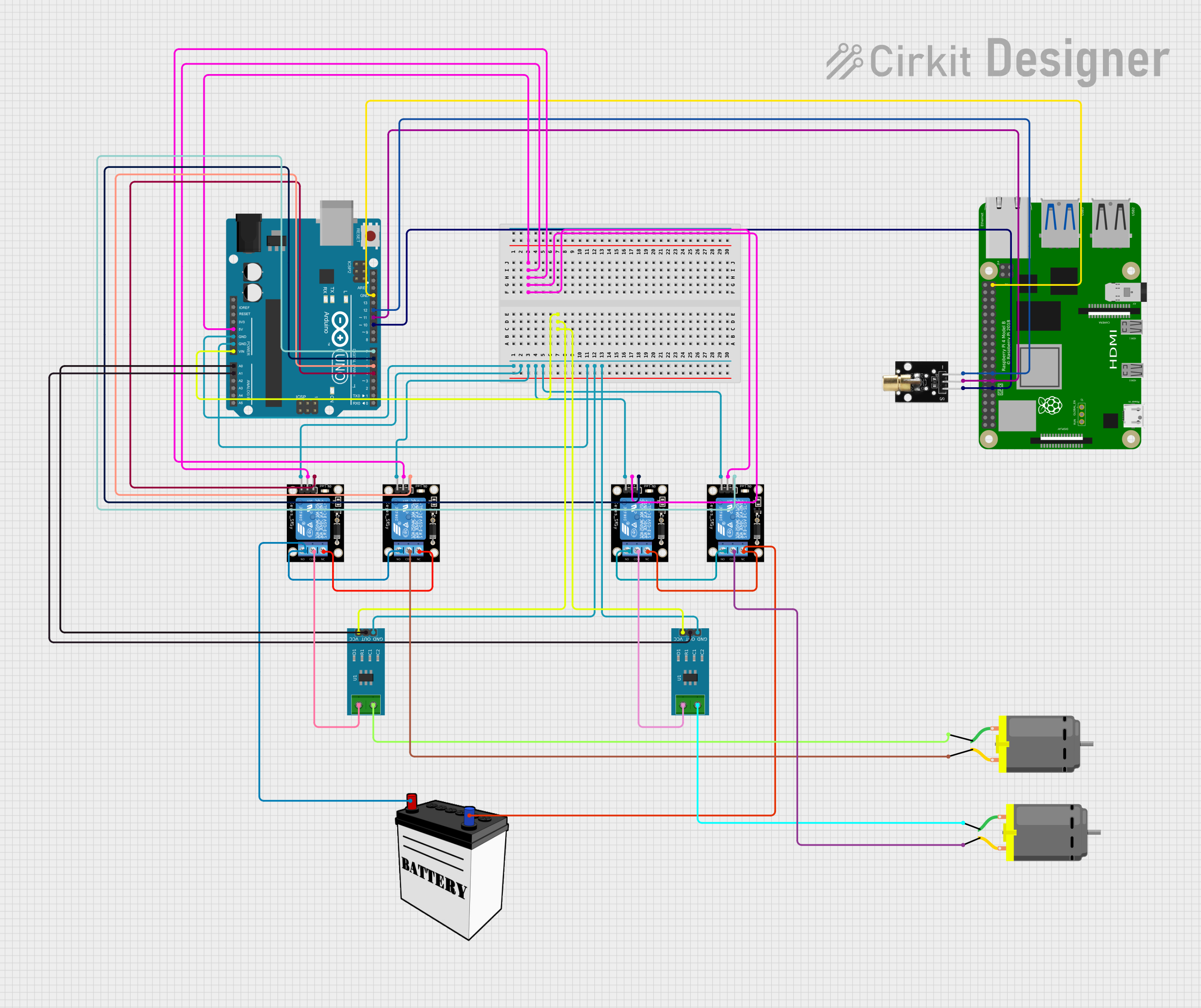
This circuit integrates a variety of components including an Arduino UNO, multiple relay modules, current sensors, a Raspberry Pi 4B, a KY-008 Laser Emitter, a 12V battery, and DC motors. The Arduino UNO serves as the primary microcontroller, interfacing with relay modules to control the DC motors and reading data from current sensors. The Raspberry Pi 4B is also included in the circuit, potentially for higher-level control or communication. The KY-008 Laser Emitter is controlled via GPIO pins from both the Arduino and Raspberry Pi. The 12V battery provides power to the relay modules and the DC motors through the relay contacts.
Component List
- Arduino UNO: A microcontroller board based on the ATmega328P. It has a variety of digital and analog I/O pins.
- Relay Module 1 Channel: An electrically operated switch that allows you to control a high power circuit with a low power signal.
- Current Sensor 5A: A sensor that measures the current flowing through it and outputs a signal proportional to the current.
- 12V Battery: Provides the power source for the motors and relay modules.
- DC Motor: An electric motor that runs on direct current (DC) electricity.
- Raspberry Pi 4B: A small computer that can be used for electronics projects or as a desktop computer.
- KY-008 Laser Emitter: A module that emits a small laser beam when powered.
Wiring Details
Arduino UNO
- 5V: Connected to the 5V pins of all relay modules.
- Vin: Connected to the VCC pins of both current sensors.
- GND: Common ground with relay modules, current sensors, Raspberry Pi 4B, and KY-008 Laser Emitter.
- Digital Pins (D4-D7): Control signals for the relay modules.
- Analog Pins (A0-A1): Connected to the OUT pins of the current sensors.
- Digital Pins (D10-D12): Connected to the SIG, 5V, and GND pins of the KY-008 Laser Emitter, respectively.
Relay Module 1 Channel
- 5V: Powered by the 5V output from the Arduino UNO.
- GND: Common ground with Arduino UNO.
- S (Signal): Controlled by digital pins D4-D7 on the Arduino UNO.
- NC (Normally Closed): Connected to the ground of the 12V battery.
- COM (Common): Connected to the DC motors and current sensors.
- NO (Normally Open): Interconnected between relay modules and connected to the 12V battery VCC.
Current Sensor 5A
- VCC: Powered by the Vin pin of the Arduino UNO.
- GND: Common ground with Arduino UNO.
- OUT: Connected to analog pins A0 and A1 on the Arduino UNO.
- Pins 1 and 2: Connected to the COM pin of the relay modules and the DC motors, respectively.
12V Battery
- VCC: Connected to the NO pins of the relay modules.
- GND: Connected to the NC pins of the relay modules.
DC Motor
- Pin 1: Connected to pin 2 of the current sensors.
- Pin 2: Connected to the COM pin of the relay modules.
Raspberry Pi 4B
- GPIO17, GPIO27, GPIO22: Connected to the SIG, 5V, and GND pins of the KY-008 Laser Emitter, respectively.
- GND: Common ground with Arduino UNO.
KY-008 Laser Emitter
- SIG: Controlled by D10 on the Arduino UNO and GPIO17 on the Raspberry Pi 4B.
- 5V: Powered by D11 on the Arduino UNO and GPIO27 on the Raspberry Pi 4B.
- GND: Common ground with D12 on the Arduino UNO and GPIO22 on the Raspberry Pi 4B.
Documented Code
Arduino UNO Code (sketch.ino)
void setup() {
  // put your setup code here, to run once:

}

void loop() {
  // put your main code here, to run repeatedly:

}
Note: The provided code for the Arduino UNO is a template with empty setup and loop functions. The actual implementation should include initialization of the I/O pins and the logic for controlling the relay modules, reading from the current sensors, and communicating with the KY-008 Laser Emitter.
Raspberry Pi 4B Code
No code was provided for the Raspberry Pi 4B. It is assumed that the user will develop the code as per the requirements of the project.
Additional Documentation (documentation.txt)
No additional documentation was provided.