
ESP32-Based Voltage Monitoring System with Buzzer Alert and Limit Switch Reset
View and Edit Project In Cirkit Designer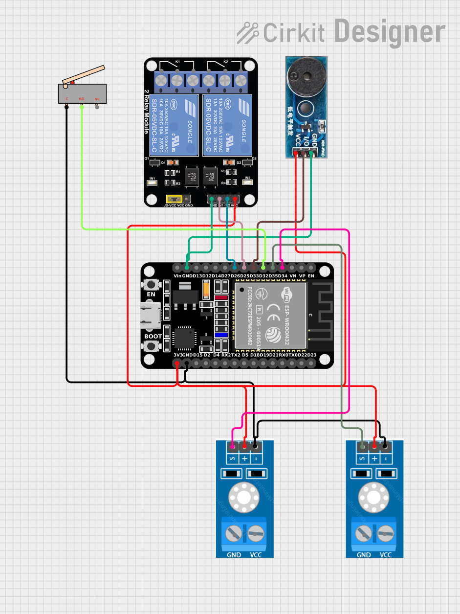
Circuit Documentation
Summary
This circuit involves an ESP32 microcontroller connected to two voltage sensors, a buzzer, two relays, and a limit switch. The ESP32 monitors voltage readings from the sensors and activates the buzzer if the readings exceed a certain threshold. The relays are controlled by the ESP32, and the limit switch is used to reset the system.
Component List
Relay Module 2 Channel
- Description: A module with two relays for switching high-power devices.
- Pins: GND, IN1, IN2, VCC, NC1, COM, NO1, NC2, NO2
Voltage Sensor
- Description: A sensor to measure voltage levels.
- Pins: GND, VCC, Output, Vcc
ESP32 (30 pin)
- Description: A microcontroller with Wi-Fi and Bluetooth capabilities.
- Pins: EN, VP, VN, D34, D35, D32, D33, D25, D26, D27, D14, D12, D13, GND, Vin, D23, D22, TX0, RX0, D21, D19, D18, D5, TX2, RX2, D4, D2, D15, 3V3
Buzzer Module
- Description: A module to produce sound.
- Pins: GND, Vcc, I/O
Limit Switch
- Description: A switch to detect physical limits or positions.
- Pins: C, NO, NC
Wiring Details
Relay Module 2 Channel
- GND connected to ESP32 GND and Buzzer Module GND
- IN1 connected to ESP32 D25
- IN2 connected to ESP32 D26
- VCC connected to ESP32 3V3, Voltage Sensor Vcc (both sensors), and Buzzer Module Vcc
Voltage Sensor 1
- GND connected to ESP32 GND and Limit Switch C
- VCC connected to ESP32 3V3
- Output connected to ESP32 D34
Voltage Sensor 2
- GND connected to ESP32 GND and Limit Switch C
- VCC connected to ESP32 3V3
- Output connected to ESP32 D35
ESP32 (30 pin)
- GND connected to Relay Module GND, Buzzer Module GND, Voltage Sensor GND (both sensors), and Limit Switch C
- D25 connected to Relay Module IN1
- D26 connected to Relay Module IN2
- 3V3 connected to Relay Module VCC, Voltage Sensor Vcc (both sensors), and Buzzer Module Vcc
- D34 connected to Voltage Sensor 1 Output
- D35 connected to Voltage Sensor 2 Output
- D32 connected to Limit Switch NO
- D33 connected to Buzzer Module I/O
Buzzer Module
- GND connected to ESP32 GND and Relay Module GND
- Vcc connected to ESP32 3V3, Relay Module VCC, and Voltage Sensor Vcc (both sensors)
- I/O connected to ESP32 D33
Limit Switch
- C connected to ESP32 GND and Voltage Sensor GND (both sensors)
- NO connected to ESP32 D32
Code Documentation
/*
 * This Arduino Sketch is for an ESP32 connected to 2 voltage sensors, a buzzer,
 * 2 relays, and a limit switch. The ESP32 counts voltage readings > 3V from
 * each sensor. If either sensor reaches a count of 10, the buzzer sounds every
 * 0.5 seconds. The buzzer stops and the count resets when the limit switch is
 * pressed.
 */

const int voltageSensor1Pin = 34; // Voltage sensor 1 output pin
const int voltageSensor2Pin = 35; // Voltage sensor 2 output pin
const int relay1Pin = 25;         // Relay 1 control pin
const int relay2Pin = 26;         // Relay 2 control pin
const int buzzerPin = 33;         // Buzzer control pin
const int limitSwitchPin = 32;    // Limit switch pin

int count1 = 0; // Counter for voltage sensor 1
int count2 = 0; // Counter for voltage sensor 2
bool buzzerState = false; // Buzzer state
unsigned long lastBuzzerToggle = 0; // Last time the buzzer toggled

void setup() {
  pinMode(voltageSensor1Pin, INPUT);
  pinMode(voltageSensor2Pin, INPUT);
  pinMode(relay1Pin, OUTPUT);
  pinMode(relay2Pin, OUTPUT);
  pinMode(buzzerPin, OUTPUT);
  pinMode(limitSwitchPin, INPUT_PULLUP);
  digitalWrite(relay1Pin, LOW);
  digitalWrite(relay2Pin, LOW);
  digitalWrite(buzzerPin, LOW);
}

void loop() {
  if (digitalRead(limitSwitchPin) == LOW) {
    count1 = 0;
    count2 = 0;
    buzzerState = false;
    digitalWrite(buzzerPin, LOW);
  }

  if (analogRead(voltageSensor1Pin) > 3.0 * 4095 / 3.3) {
    count1++;
  }

  if (analogRead(voltageSensor2Pin) > 3.0 * 4095 / 3.3) {
    count2++;
  }

  if (count1 >= 10 || count2 >= 10) {
    unsigned long currentMillis = millis();
    if (currentMillis - lastBuzzerToggle >= 500) {
      buzzerState = !buzzerState;
      digitalWrite(buzzerPin, buzzerState ? HIGH : LOW);
      lastBuzzerToggle = currentMillis;
    }
  }
}
This code initializes the pins for the voltage sensors, relays, buzzer, and limit switch. It continuously monitors the voltage sensors and increments counters if the voltage exceeds 3V. If either counter reaches 10, the buzzer toggles every 0.5 seconds. Pressing the limit switch resets the counters and stops the buzzer.