
ESP32-Based Load Cell Weight Measurement System with Indicator LEDs
View and Edit Project In Cirkit Designer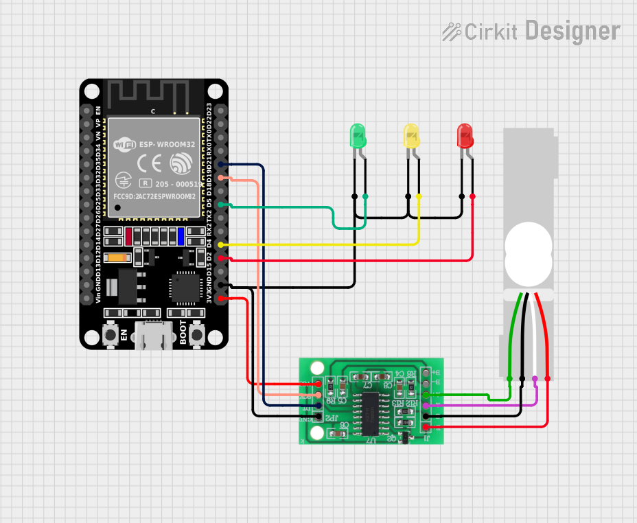
Circuit Documentation
Summary of the Circuit
This circuit is designed to interface an ESP32 microcontroller with an HX711 bridge sensor interface and a load cell. The HX711 is used to amplify and convert the load cell signals into a digital form that the ESP32 can process. Additionally, the circuit includes three LEDs (red, green, and yellow) that can be controlled by the ESP32 for indication purposes. The ESP32 powers the HX711 and the LEDs are connected to GPIO pins with their cathodes tied to the ground.
Component List
ESP32 (30 pin)
- Description: A microcontroller with Wi-Fi and Bluetooth capabilities, featuring a wide range of GPIO pins.
- Pins: EN, VP, VN, D34, D35, D32, D33, D25, D26, D27, D14, D12, D13, GND, Vin, D23, D22, TX0, RX0, D21, D19, D18, D5, TX2, RX2, D4, D2, D15, 3V3
Load Cell - Red/white/black/green
- Description: A transducer that converts force into an electrical signal.
- Pins: E+, A-, E-, A+
HX711 - Bridge Sensor Interface
- Description: A precision 24-bit analog-to-digital converter (ADC) designed for weigh scales and industrial control applications to interface directly with a bridge sensor.
- Pins: E+, E-, A-, A+, B-, B+, GND - GROUND, DATA (OUT), SCK - CLOCK (IN), 3.3/3.5V Supply
LED: Two Pin (red)
- Description: A red indicator light.
- Pins: cathode, anode
LED: Two Pin (green)
- Description: A green indicator light.
- Pins: cathode, anode
LED: Two Pin (yellow)
- Description: A yellow indicator light.
- Pins: cathode, anode
Wiring Details
ESP32 (30 pin)
- D21 connected to HX711 DATA (OUT)
- D19 connected to HX711 SCK - CLOCK (IN)
- D5 connected to Green LED anode
- D4 connected to Yellow LED anode
- D2 connected to Red LED anode
- GND connected to all LED cathodes, HX711 GND - GROUND
- 3V3 connected to HX711 3.3/3.5V Supply
Load Cell - Red/white/black/green
- E+ connected to HX711 E+
- A- connected to HX711 A-
- E- connected to HX711 E-
- A+ connected to HX711 A+
HX711 - Bridge Sensor Interface
- E+ connected to Load Cell E+
- E- connected to Load Cell E-
- A- connected to Load Cell A-
- A+ connected to Load Cell A+
- GND - GROUND connected to ESP32 GND
- DATA (OUT) connected to ESP32 D21
- SCK - CLOCK (IN) connected to ESP32 D19
- 3.3/3.5V Supply connected to ESP32 3V3
LED: Two Pin (red)
- anode connected to ESP32 D2
- cathode connected to ESP32 GND
LED: Two Pin (green)
- anode connected to ESP32 D5
- cathode connected to ESP32 GND
LED: Two Pin (yellow)
- anode connected to ESP32 D4
- cathode connected to ESP32 GND
Documented Code
Since no code was provided, this section is left blank. The code would typically include initialization and configuration of the ESP32 GPIO pins, setup for the HX711 interface, and logic for reading the load cell data and controlling the LEDs based on certain conditions or thresholds.