
Arduino Mega 2560-Based Obstacle-Avoiding Robot with Ultrasonic Sensors and Motor Drivers
View and Edit Project In Cirkit Designer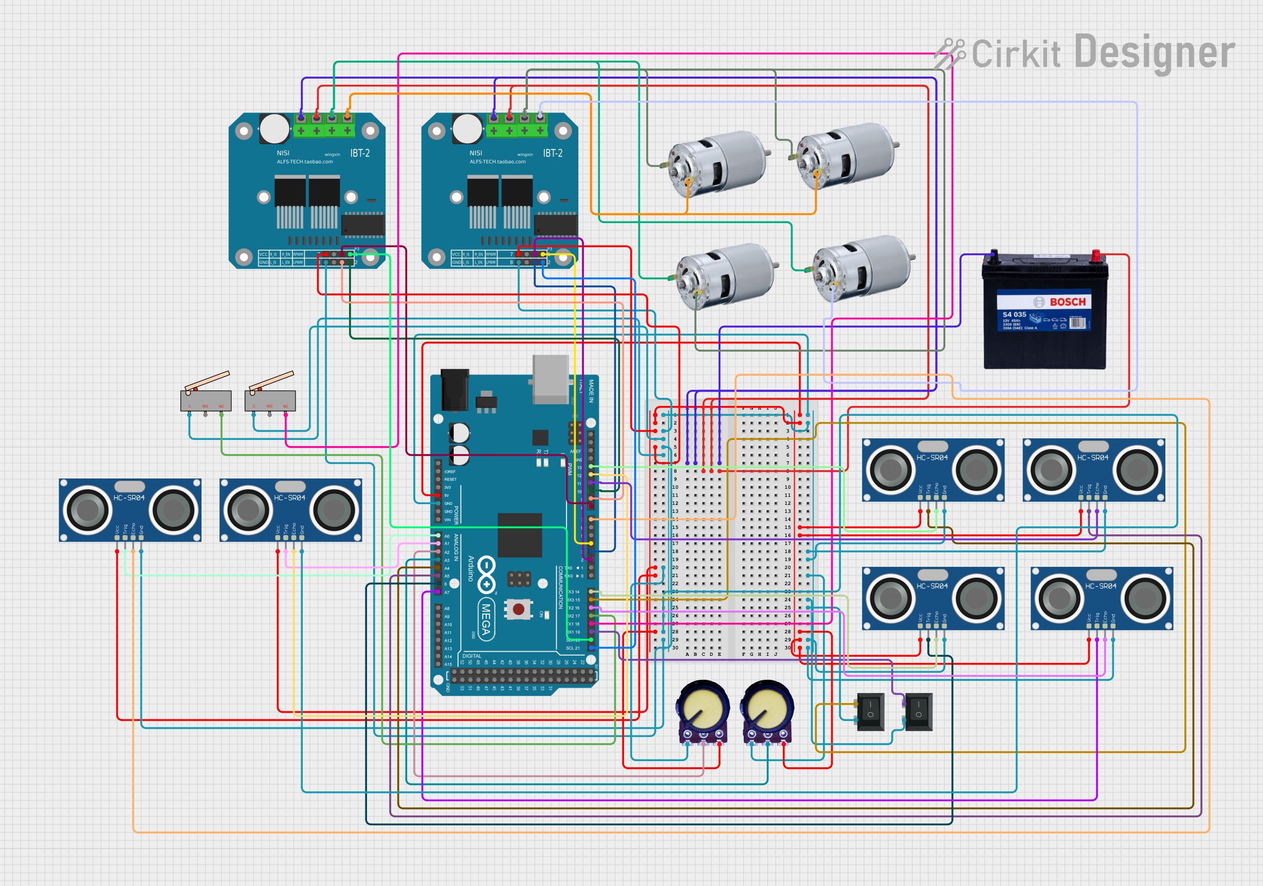
Circuit Documentation
Summary
This document provides a detailed overview of a circuit designed to control motors and detect obstacles using an Arduino Mega 2560 microcontroller. The circuit includes motor drivers, ultrasonic sensors, limit switches, potentiometers, and a battery. The Arduino Mega 2560 is programmed to control the motors and read sensor data to navigate and avoid obstacles.
Component List
BTS7960 Motor Driver
- Description: High-power motor driver module.
- Pins: Pin 1, Pin 2, Pin 3, Pin 4, Pin 5, Pin 6, Pin 7, Pin 8, Pin 9, Pin 10, Pin 11, Pin 12
12V 200Ah Battery
- Description: Power source for the circuit.
- Pins: GND, 12V
HC-SR04 Ultrasonic Sensor
- Description: Ultrasonic distance sensor.
- Pins: VCC, TRIG, ECHO, GND
Limit Switch
- Description: Mechanical switch for detecting limits.
- Pins: C, NO, NC
Arduino Mega 2560
- Description: Microcontroller board.
- Pins: IOREF, RESET, 3V3, 5V, GND, VIN, A0, A1, A2, A3, A4, A5, A6, A7, A8, A9, A10, A11, A12, A13, A14, A15, D21/SCL, D20/SDA, D19/RX1, D18/TX1, D17 PWM/RX2, D16 PWM/TX2, D15/RX3, D14/TX3, D0 RX0, D1 TX0, D2 PWM, D3 PWM, D4 PWM, D5 PWM, D6 PWM, D7 PWM, D8 PWM, D9 PWM, D10 PWM, D11 PWM, D12 PWM, D13 PWM, AREF, SDA, SCL, D52, D50, D48, D46, D44, D42, D40, D38, D36, D34, D32, D30, D28, D26, D24, D22, D53, D51, D49, D47, D45, D43, D41, D39, D37, D35, D33, D31, D29, D27, D25, D23
775 Motor
- Description: High-torque DC motor.
- Pins: positive, negative
Potentiometer
- Description: Variable resistor for adjusting voltage.
- Pins: GND, Output, VCC
Rocker Switch (SPST)
- Description: Single-pole single-throw switch.
- Pins: 1, 2
Wiring Details
BTS7960 Motor Driver
- Pin 12: Connected to GND of the 12V 200Ah Battery.
- Pin 11: Connected to 12V of the 12V 200Ah Battery.
- Pin 5: Connected to 5V of the Arduino Mega 2560.
- Pin 1: Connected to GND of the Arduino Mega 2560.
- Pin 4: Connected to D21/SCL of the Arduino Mega 2560.
- Pin 8: Connected to D20/SDA of the Arduino Mega 2560.
- Pin 7: Connected to D2 PWM of the Arduino Mega 2560.
- Pin 3: Connected to D3 PWM of the Arduino Mega 2560.
- Pin 9: Connected to the negative pin of the 775 motor.
- Pin 10: Connected to the positive pin of the 775 motor.
12V 200Ah Battery
- GND: Connected to Pin 12 of the BTS7960 Motor Driver.
- 12V: Connected to Pin 11 of the BTS7960 Motor Driver.
HC-SR04 Ultrasonic Sensor
- VCC: Connected to 5V of the Arduino Mega 2560.
- TRIG: Connected to A0, A1, A4, A5, A6, A7 of the Arduino Mega 2560.
- ECHO: Connected to D7, D12, D13, D11, D14, D16 of the Arduino Mega 2560.
- GND: Connected to GND of the Arduino Mega 2560.
Limit Switch
- C: Connected to GND of the Arduino Mega 2560.
- NC: Connected to D18/TX1 and D17 PWM/RX2 of the Arduino Mega 2560.
Arduino Mega 2560
- 5V: Connected to Pin 5 of the BTS7960 Motor Driver.
- GND: Connected to Pin 1 of the BTS7960 Motor Driver.
- A0: Connected to TRIG of the HC-SR04 Ultrasonic Sensor.
- A1: Connected to TRIG of the HC-SR04 Ultrasonic Sensor.
- A2: Connected to Output of the Potentiometer.
- A3: Connected to Output of the Potentiometer.
- A4: Connected to TRIG of the HC-SR04 Ultrasonic Sensor.
- A5: Connected to TRIG of the HC-SR04 Ultrasonic Sensor.
- A6: Connected to TRIG of the HC-SR04 Ultrasonic Sensor.
- A7: Connected to TRIG of the HC-SR04 Ultrasonic Sensor.
- D21/SCL: Connected to Pin 4 of the BTS7960 Motor Driver.
- D20/SDA: Connected to Pin 8 of the BTS7960 Motor Driver.
- D19/RX1: Connected to pin 2 of the Rocker Switch (SPST).
- D18/TX1: Connected to NC of the Limit Switch.
- D17 PWM/RX2: Connected to NC of the Limit Switch.
- D16 PWM/TX2: Connected to ECHO of the HC-SR04 Ultrasonic Sensor.
- D15/RX3: Connected to pin 2 of the Rocker Switch (SPST).
- D14/TX3: Connected to ECHO of the HC-SR04 Ultrasonic Sensor.
- D2 PWM: Connected to Pin 7 of the BTS7960 Motor Driver.
- D3 PWM: Connected to Pin 3 of the BTS7960 Motor Driver.
- D4 PWM: Connected to Pin 8 of the BTS7960 Motor Driver.
- D7 PWM: Connected to ECHO of the HC-SR04 Ultrasonic Sensor.
- D8 PWM: Connected to Pin 7 of the BTS7960 Motor Driver.
- D9 PWM: Connected to Pin 3 of the BTS7960 Motor Driver.
- D10 PWM: Connected to Pin 4 of the BTS7960 Motor Driver.
- D11 PWM: Connected to ECHO of the HC-SR04 Ultrasonic Sensor.
- D12 PWM: Connected to ECHO of the HC-SR04 Ultrasonic Sensor.
- D13 PWM: Connected to ECHO of the HC-SR04 Ultrasonic Sensor.
775 Motor
- positive: Connected to Pin 10 of the BTS7960 Motor Driver.
- negative: Connected to Pin 9 of the BTS7960 Motor Driver.
Potentiometer
- GND: Connected to GND of the Arduino Mega 2560.
- Output: Connected to A2 and A3 of the Arduino Mega 2560.
- VCC: Connected to 5V of the Arduino Mega 2560.
Rocker Switch (SPST)
- 1: Connected to GND of the Arduino Mega 2560.
- 2: Connected to D19/RX1 and D15/RX3 of the Arduino Mega 2560.
Documented Code
// Motor Pins
int R1_en = 2;
int L1_en = 3;
int R_pwm = 4;
int R2_en = 8;
int L2_en = 9;
int L_pwm = 10;

// Relay Pins
int R_Relay = 5;
int L_Relay = 6;

// Potentiometer Pins
const int xMaxPin = A2; // Potentiometer for X max
const int yMaxPin = A3; // Potentiometer for Y max

// Ultrasonic Sensor Pins
const int trigPins[6] = {A0, A1, A4, A5, A6, A7}; // Trigger pins for 6 ultrasonic sensors
const int echoPins[6] = {7, 12, 13, 11, 14, 16};   // Echo pins for 6 ultrasonic sensors

// Limit Switch Pins
const int limitSwitchLeft = 17;
const int limitSwitchRight = 18;

// Button Pin
const int buttonPin = 15;

// Global Variables
int