
ESP32-WROOM-32UE Controlled Battery-Powered Robotic Car with Ultrasonic Sensor and LED Indicators
View and Edit Project In Cirkit Designer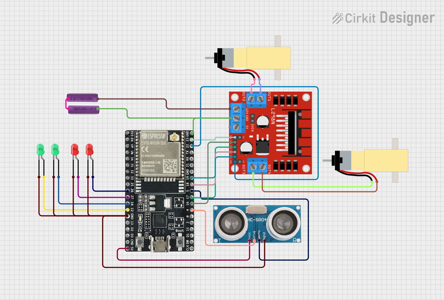
Circuit Documentation
Summary
This document provides a detailed overview of a circuit that includes an ESP32 microcontroller, multiple LEDs, an ultrasonic sensor, a DC motor driver, hobby gearmotors, and batteries. The circuit is designed to control LEDs, read distance measurements from the ultrasonic sensor, and drive motors using the L298N motor driver.
Component List
ESP32-WROOM-32UE
- Description: A powerful microcontroller with Wi-Fi and Bluetooth capabilities.
- Pins: 3v3, EN, VP, VN, 34, 35, 32, 33, 25, 26, 27, 14, 12, GND, 13, D2, D3, 5V, 23, 22, TX, RX, 21, 19, 18, 5, 17, 16, 4, 0, 2, 15, D1, D0, CKL
LED: Two Pin (red)
- Description: A red LED with two pins.
- Pins: cathode, anode
LED: Two Pin (green)
- Description: A green LED with two pins.
- Pins: cathode, anode
Ultrasonic Sensor
- Description: A sensor used to measure distance using ultrasonic waves.
- Pins: +VCC, Trigger, Echo, GND
L298N DC motor driver
- Description: A dual H-bridge motor driver that can control the speed and direction of two DC motors.
- Pins: OUT1, OUT2, 12V, GND, 5V, OUT3, OUT4, 5V-ENA-JMP-I, 5V-ENA-JMP-O, +5V-J1, +5V-J2, ENA, IN1, IN2, IN3, IN4, ENB
3.7v battery
- Description: A 3.7V rechargeable battery.
- Pins: +, -
Hobby Gearmotor with 48:1 gearbox
- Description: A small DC motor with a 48:1 gearbox for increased torque.
- Pins: pin 1, pin 2
Wiring Details
ESP32-WROOM-32UE
- Pin 26 is connected to the anode of a red LED.
- Pin 27 is connected to the anode of another red LED.
- Pin 14 is connected to the anode of a green LED.
- Pin 12 is connected to the anode of another green LED.
- GND is connected to the cathodes of all LEDs and the GND of the Ultrasonic Sensor.
- 5V is connected to the +VCC of the Ultrasonic Sensor.
- Pin 23 is connected to the ENA of the L298N DC motor driver.
- Pin 22 is connected to the ENB of the L298N DC motor driver.
- Pin 19 is connected to the IN4 of the L298N DC motor driver.
- Pin 18 is connected to the IN3 of the L298N DC motor driver.
- Pin 5 is connected to the Echo of the Ultrasonic Sensor.
- Pin 17 is connected to the IN2 of the L298N DC motor driver.
- Pin 16 is connected to the IN1 of the L298N DC motor driver.
- Pin 4 is connected to the Trigger of the Ultrasonic Sensor.
LED: Two Pin (red)
- Anode is connected to Pin 26 of the ESP32.
- Cathode is connected to GND.
LED: Two Pin (red)
- Anode is connected to Pin 27 of the ESP32.
- Cathode is connected to GND.
LED: Two Pin (green)
- Anode is connected to Pin 14 of the ESP32.
- Cathode is connected to GND.
LED: Two Pin (green)
- Anode is connected to Pin 12 of the ESP32.
- Cathode is connected to GND.
Ultrasonic Sensor
- +VCC is connected to 5V of the ESP32.
- Trigger is connected to Pin 4 of the ESP32.
- Echo is connected to Pin 5 of the ESP32.
- GND is connected to GND.
L298N DC motor driver
- GND is connected to GND of the ESP32 and GND of a 3.7v battery.
- ENA is connected to Pin 23 of the ESP32.
- ENB is connected to Pin 22 of the ESP32.
- IN4 is connected to Pin 19 of the ESP32.
- IN3 is connected to Pin 18 of the ESP32.
- IN2 is connected to Pin 17 of the ESP32.
- IN1 is connected to Pin 16 of the ESP32.
- OUT1 is connected to pin 2 of a Hobby Gearmotor.
- OUT2 is connected to pin 1 of a Hobby Gearmotor.
- OUT3 is connected to pin 1 of another Hobby Gearmotor.
- OUT4 is connected to pin 2 of another Hobby Gearmotor.
- 12V is connected to the + of a 3.7v battery.
3.7v battery
- - is connected to GND of the ESP32 and GND of the L298N DC motor driver.
- + is connected to 12V of the L298N DC motor driver.
3.7v battery
- - is connected to + of another 3.7v battery.
Hobby Gearmotor with 48:1 gearbox
- Pin 2 is connected to OUT1 of the L298N DC motor driver.
- Pin 1 is connected to OUT2 of the L298N DC motor driver.
Hobby Gearmotor with 48:1 gearbox
- Pin 1 is connected to OUT3 of the L298N DC motor driver.
- Pin 2 is connected to OUT4 of the L298N DC motor driver.
Code
No code is provided for this circuit.