Cirkit Designer
Your all-in-one circuit design IDE
Home /
Project Documentation
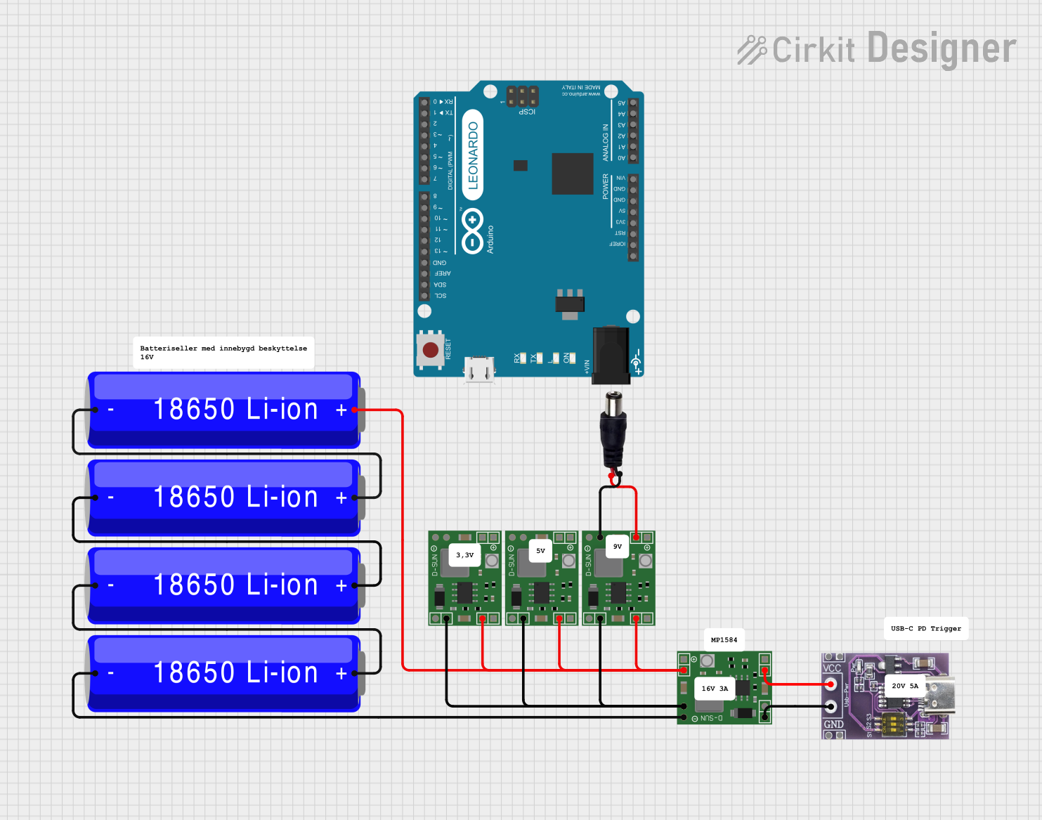
Battery-Powered USB-C PD Trigger with MP1584EN Power Regulation
Circuit Documentation
Summary
This document provides a detailed overview of a circuit that includes a USB-C PD Trigger Board, multiple 18650 Li-ion Batteries, MP1584EN Power Regulator Boards, an Arduino Leonardo, and a power jack. The circuit is designed to manage power distribution and regulation, with connections between various components to ensure proper functionality.
Component List
USB-C PD Trigger Board
- Description: A board used to trigger USB-C Power Delivery.
- Pins: VCC, GND
18650 Li-ion Battery
- Description: Rechargeable lithium-ion battery.
- Pins: +, -
MP1584EN Power Regulator Board
- Description: A power regulator board used to step down voltage.
- Pins: IN +, IN -, OUT +, OUT -
Arduino Leonardo (Rev3b)
- Description: A microcontroller board based on the ATmega32u4.
- Pins: D0/RX, D1/TX, D2/SDA, D3 PWM/SCL, D4/A6, D5 PWM, D6 PWM/A7, D7, n.c., IOREF, RESET, 3V3, 5V, GND, VIN, A0, A1, A2, A3, A4, A5, D8/A8, D9 PWM/A9, D10 PWM/A10, D11 PWM, D12/A11, D13 PWM, AREF, SDA, SCL
Power Jack
- Description: A jack for connecting an external power source.
- Pins: POSITIF, NEGATIF
Comment
- Description: Placeholder for comments in the circuit.
- Pins: None
Wiring Details
USB-C PD Trigger Board
- VCC is connected to IN + of the MP1584EN Power Regulator Board.
- GND is connected to IN - of the MP1584EN Power Regulator Board.
18650 Li-ion Battery
- - of one battery is connected to + of another battery.
- + of the first battery is connected to:
- IN + of the MP1584EN Power Regulator Board.
- OUT + of the MP1584EN Power Regulator Board.
- IN + of another MP1584EN Power Regulator Board.
- IN + of yet another MP1584EN Power Regulator Board.
- - of the second battery is connected to + of a third battery.
- + of the third battery is connected to - of the fourth battery.
- OUT - of the MP1584EN Power Regulator Board is connected to - of the fourth battery.
MP1584EN Power Regulator Board
- IN + of one board is connected to VCC of the USB-C PD Trigger Board.
- IN - of the same board is connected to GND of the USB-C PD Trigger Board.
- IN + of another board is connected to + of the first 18650 Li-ion Battery.
- OUT + of the same board is connected to IN + of another MP1584EN Power Regulator Board.
- IN - of the same board is connected to OUT - of the first MP1584EN Power Regulator Board.
- OUT + of another board is connected to POSITIF of the power jack.
- OUT - of the same board is connected to NEGATIF of the power jack.
Arduino Leonardo (Rev3b)
- No specific connections provided in the net list.
Power Jack
- POSITIF is connected to OUT + of the MP1584EN Power Regulator Board.
- NEGATIF is connected to OUT - of the MP1584EN Power Regulator Board.
Code
No code is provided for the microcontrollers in this circuit.
This documentation provides a comprehensive overview of the components and their connections within the circuit. Each component is described, and detailed wiring information is provided to ensure proper assembly and functionality.