ESP8266 and Arduino Mega 2560 Based Access Control System with Dual Authentication
Circuit Documentation
Summary
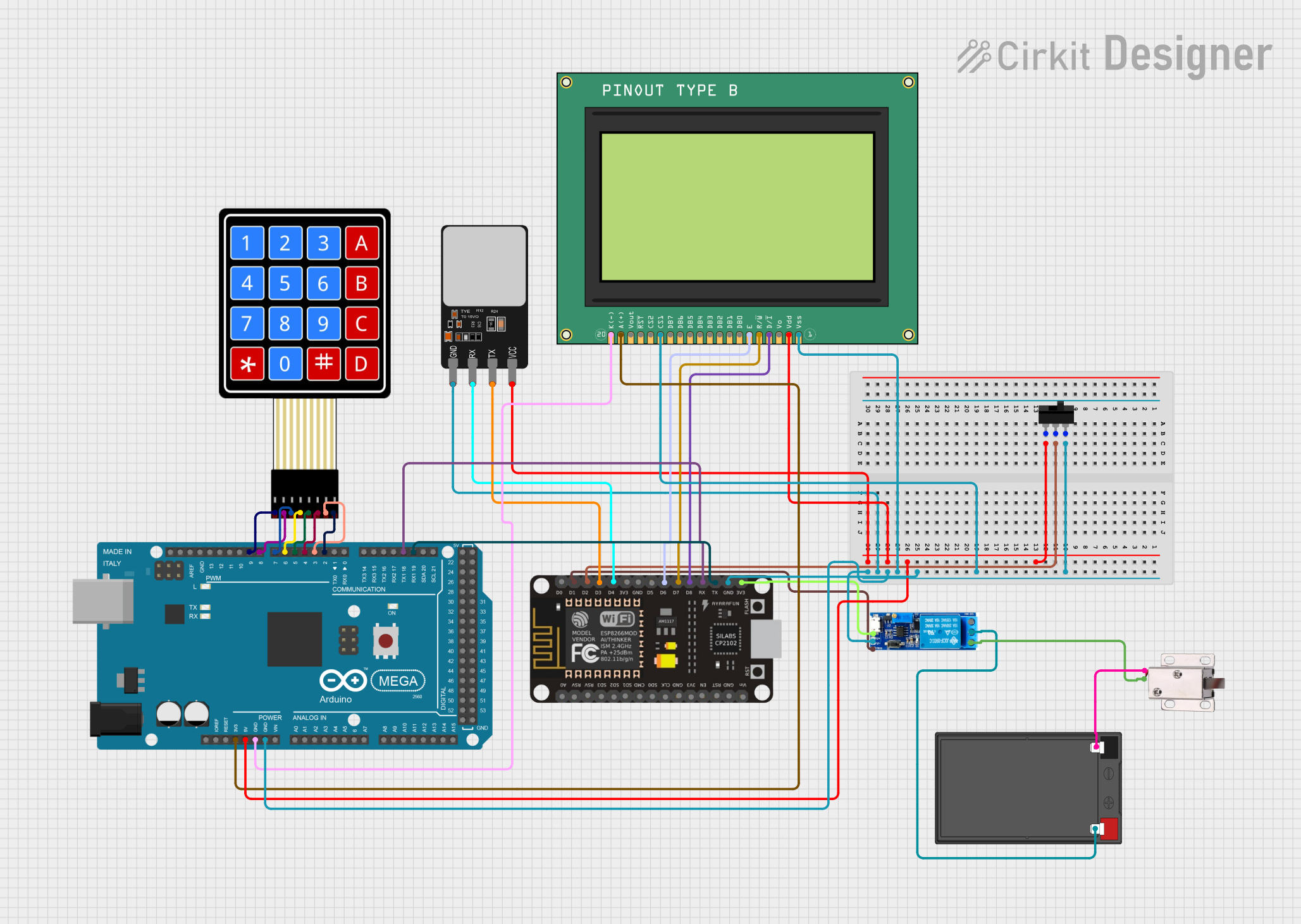
This circuit integrates a variety of components including microcontrollers, a relay module, a toggle switch, a battery, a solenoid lock, a keypad, a fingerprint scanner, and a graphic LCD display. The primary control is handled by an ESP8266 NodeMCU and an Arduino Mega 2560, which communicate with each other and with the other components to perform specific functions. The relay module is used to control the power to the solenoid lock, which is powered by a 12V battery. The toggle switch and various connections to the microcontrollers manage the control logic and user interface elements such as the keypad, fingerprint scanner, and LCD display.
Component List
ESP8266 NodeMCU
- Microcontroller with WiFi capabilities.
- Pins: D0-D8, RX, TX, A0, RSV, SD3, SD2, SD1, CMD, SD0, CLK, EN, RST, VIN, 3V3, GND.
Toggle Switch
- A simple switch with three terminals: L1, COM, L2.
Relay Module 5V-30V
- An electrically operated switch that allows control of a high voltage circuit by a low voltage signal.
- Pins: common contact, normally open, normally closed, trigger, V-, V+.
12V 7Ah Battery
- A rechargeable battery providing a 12V output.
- Pins: 12v +, 12v -.
12V Solenoid Lock
- An electronic lock that can be controlled via an electrical signal.
- Pins: VCC, GND.
Arduino Mega 2560
- A microcontroller board based on the ATmega2560.
- Pins: IOREF, RESET, 3V3, 5V, GND, VIN, A0-A15, D0-D53, AREF, SDA, SCL.
4X4 Membrane Matrix Keypad
- An input device consisting of a matrix of buttons.
- Pins: R1-R4, C1-C4.
Fingerprint Scanner
- A biometric sensor for fingerprint detection and verification.
- Pins: VCC, TX, RX, GND.
Graphic LCD Display (GLCD 128x64)
- A graphical display capable of displaying text and images.
- Pins: Vss, Vdd, Vo, D/I, R/W, Enable, DB0-DB7, CS1, CS2, RST, Vout, A(+), K(-).
Wiring Details
ESP8266 NodeMCU
- GND connected to the common ground net.
- D1 connected to the trigger pin of the Relay Module.
- D2 connected to the COM pin of the Toggle Switch.
- D3 connected to the TX pin of the Fingerprint Scanner.
- D4 connected to the RX pin of the Fingerprint Scanner.
- D6 connected to the Enable pin of the GLCD.
- D7 connected to the R/W pin of the GLCD.
- D8 connected to the D/I pin of the GLCD.
- RX connected to the TX1 pin of the Arduino Mega 2560.
- TX connected to the RX1 pin of the Arduino Mega 2560.
- 3V3 connected to the V+ pin of the Relay Module.
Toggle Switch
- L1 connected to the 5V pin of the Arduino Mega 2560 and Vdd pin of the GLCD.
- COM connected to the D2 pin of the ESP8266 NodeMCU.
- L2 connected to the common ground net.
Relay Module 5V-30V
- common contact connected to the 12v + pin of the 12V Battery.
- normally open connected to the VCC pin of the 12V Solenoid Lock.
- trigger connected to the D1 pin of the ESP8266 NodeMCU.
- V- connected to the common ground net.
- V+ connected to the 3V3 pin of the ESP8266 NodeMCU.
12V 7Ah Battery
- 12v + connected to the common contact pin of the Relay Module.
- 12v - connected to the GND pin of the 12V Solenoid Lock.
12V Solenoid Lock
- VCC connected to the normally open pin of the Relay Module.
- GND connected to the 12v - pin of the 12V Battery.
Arduino Mega 2560
- GND connected to the common ground net.
- 5V connected to the L1 pin of the Toggle Switch.
- 3V3 connected to the A(+) pin of the GLCD.
- D2-D9 PWM connected to the C1-C4 and R1-R4 pins of the 4X4 Membrane Matrix Keypad.
- TX1 (D18) connected to the RX pin of the ESP8266 NodeMCU.
- RX1 (D19) connected to the TX pin of the ESP8266 NodeMCU.
4X4 Membrane Matrix Keypad
- R1-R4 connected to the D9-D6 PWM pins of the Arduino Mega 2560.
- C1-C4 connected to the D5-D2 PWM pins of the Arduino Mega 2560.
Fingerprint Scanner
- VCC connected to the L1 pin of the Toggle Switch.
- TX connected to the D3 pin of the ESP8266 NodeMCU.
- RX connected to the D4 pin of the ESP8266 NodeMCU.
- GND connected to the common ground net.
Graphic LCD Display (GLCD 128x64)
- Vss connected to the common ground net.
- Vdd connected to the L1 pin of the Toggle Switch.
- Enable connected to the D6 pin of the ESP8266 NodeMCU.
- R/W connected to the D7 pin of the ESP8266 NodeMCU.
- D/I connected to the D8 pin of the ESP8266 NodeMCU.
- A(+) connected to the 3V3 pin of the Arduino Mega 2560.
- K(-) connected to the common ground net.
Documented Code
Arduino Mega 2560 Code (sketch.ino)
void setup() {
  // put your setup code here, to run once:

}

void loop() {
  // put your main code here, to run repeatedly:

}
Note: The code provided for the Arduino Mega 2560 is a template and does not contain any functional code. It is expected that the user will add the necessary code to interact with the connected components.
ESP8266 NodeMCU Code
No code was provided for the ESP8266 NodeMCU. It is assumed that the user will provide the necessary code to control the device and its interactions with other components.