Cirkit Designer
Your all-in-one circuit design IDE
Home /
Project Documentation
Arduino UNO and L298N Motor Driver Controlled DC Motor with Encoder
Circuit Documentation
Summary
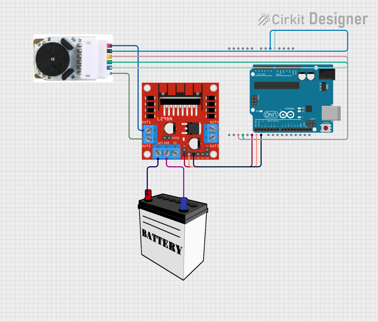
This circuit is designed to control a DC motor with an encoder using an Arduino UNO and an L298N DC motor driver. The Arduino UNO reads the encoder signals to determine the motor's position and velocity, and it uses this information to control the motor's speed and direction through the L298N motor driver. The circuit is powered by a 12V battery.
Component List
L298N DC Motor Driver
- Description: A dual H-Bridge motor driver that allows control of the speed and direction of two DC motors.
- Pins: OUT1, OUT2, 12V, GND, 5V, OUT3, OUT4, 5V-ENA-JMP-I, 5V-ENA-JMP-O, +5V-J1, +5V-J2, ENA, IN1, IN2, IN3, IN4, ENB
Arduino UNO
- Description: A microcontroller board based on the ATmega328P, used for reading sensor inputs and controlling actuators.
- Pins: UNUSED, IOREF, Reset, 3.3V, 5V, GND, Vin, A0, A1, A2, A3, A4, A5, SCL, SDA, AREF, D13, D12, D11, D10, D9, D8, D7, D6, D5, D4, D3, D2, D1, D0
DC Motor with Encoder
- Description: A DC motor equipped with an encoder to provide feedback on the motor's position and speed.
- Pins: Encoder B, Encoder A, GND - Encoder, VCC - Encoder Power, Motor +ve, Motor -ve
12V Battery
- Description: A power source providing 12V for the motor driver and motor.
- Pins: VCC, GND
Wiring Details
L298N DC Motor Driver
- OUT1 connected to Motor +ve of DC Motor with Encoder
- OUT2 connected to Motor -ve of DC Motor with Encoder
- 12V connected to VCC of 12V Battery
- GND connected to GND of 12V Battery
- ENA connected to D5 of Arduino UNO
- IN1 connected to D6 of Arduino UNO
- IN2 connected to D7 of Arduino UNO
Arduino UNO
- D5 connected to ENA of L298N DC Motor Driver
- D6 connected to IN1 of L298N DC Motor Driver
- D7 connected to IN2 of L298N DC Motor Driver
- 5V connected to VCC - Encoder Power of DC Motor with Encoder
- GND connected to GND - Encoder of DC Motor with Encoder
- D3 connected to Encoder B of DC Motor with Encoder
- D2 connected to Encoder A of DC Motor with Encoder
DC Motor with Encoder
- Motor +ve connected to OUT1 of L298N DC Motor Driver
- Motor -ve connected to OUT2 of L298N DC Motor Driver
- VCC - Encoder Power connected to 5V of Arduino UNO
- GND - Encoder connected to GND of Arduino UNO
- Encoder B connected to D3 of Arduino UNO
- Encoder A connected to D2 of Arduino UNO
12V Battery
- VCC connected to 12V of L298N DC Motor Driver
- GND connected to GND of L298N DC Motor Driver
Code Documentation
Arduino UNO Code
#include <util/atomic.h>

// Pins
#define ENCA 2
#define ENCB 3
#define PWM 5
#define IN1 6
#define IN2 7

// globals
long prevT = 0;
int posPrev = 0;
// Use the "volatile" directive for variables
// used in an interrupt
volatile int pos_i = 0;
volatile float velocity_i = 0;
volatile long prevT_i = 0;

float v1Filt = 0;
float v1Prev = 0;
float v2Filt = 0;
float v2Prev = 0;

float eintegral = 0;

void setup() {
  Serial.begin(115200);

  pinMode(ENCA, INPUT);
  pinMode(ENCB, INPUT);
  pinMode(PWM, OUTPUT);
  pinMode(IN1, OUTPUT);
  pinMode(IN2, OUTPUT);

  attachInterrupt(digitalPinToInterrupt(ENCA), readEncoder, RISING);
}

void loop() {
  // read the position in an atomic block
  // to avoid potential misreads
  int pos = 0;
  float velocity2 = 0;
  ATOMIC_BLOCK(ATOMIC_RESTORESTATE) {
    pos = pos_i;
    velocity2 = velocity_i;
  }

  // Compute velocity with method 1
  long currT = micros();
  float deltaT = ((float) (currT - prevT)) / 1.0e6;
  float velocity1 = (pos - posPrev) / deltaT;
  posPrev = pos;
  prevT = currT;

  // Convert count/s to RPM
  float v1 = velocity1 / 600.0 * 60.0;
  float v2 = velocity2 / 600.0 * 60.0;

  // Low-pass filter (25 Hz cutoff)
  v1Filt = 0.854 * v1Filt + 0.0728 * v1 + 0.0728 * v1Prev;
  v1Prev = v1;
  v2Filt = 0.854 * v2Filt + 0.0728 * v2 + 0.0728 * v2Prev;
  v2Prev = v2;

  // Set a target
  float vt = 100 * (sin(currT / 1e6) > 0);

  // Compute the control signal u
  float kp = 5;
  float ki = 10;
  float e = vt - v1Filt;
  eintegral = eintegral + e * deltaT;

  float u = kp * e + ki * eintegral;

  // Set the motor speed and direction
  int dir = 1;
  if (u < 0) {
    dir = -1;
  }
  int pwr = (int) fabs(u);
  if (pwr > 255) {
    pwr = 255;
  }
  setMotor(dir, pwr, PWM, IN1, IN2);

  Serial.print(vt);
  Serial.print(" ");
  Serial.print(v1Filt);
  Serial.println();
  delay(1);
}

void setMotor(int dir, int pwmVal, int pwm, int in1, int in2) {
  analogWrite(pwm, pwmVal); // Motor speed
  if (dir == 1) {
    // Turn one way
    digitalWrite(in1, HIGH);
    digitalWrite(in2, LOW);
  } else if (dir == -1) {
    // Turn the other way
    digitalWrite(in1, LOW);
    digitalWrite(in2, HIGH);
  } else {
    // Or don't turn
    digitalWrite(in1, LOW);
    digitalWrite(in2, LOW);
  }
}

void readEncoder() {
  // Read encoder B when ENCA rises
  int b = digitalRead(ENCB);
  int increment = 0;
  if (b > 0) {
    // If B is high, increment forward
    increment = 1;
  } else {
    // Otherwise, increment backward
    increment = -1;
  }
  pos_i = pos_i + increment;

  // Compute velocity with method 2
  long currT = micros();
  float deltaT = ((float) (currT - prevT_i)) / 1.0e6;
  velocity_i = increment / deltaT;
  prevT_i = currT;
}
This code reads the encoder signals to determine the motor's position and velocity, and it uses a PID control algorithm to adjust the motor's speed and direction to match a target velocity. The motor speed and direction are controlled through the L298N motor driver.