
ESP32 CAM-Based Impact Detection System with Serial Communication and LED Indicator
View and Edit Project In Cirkit Designer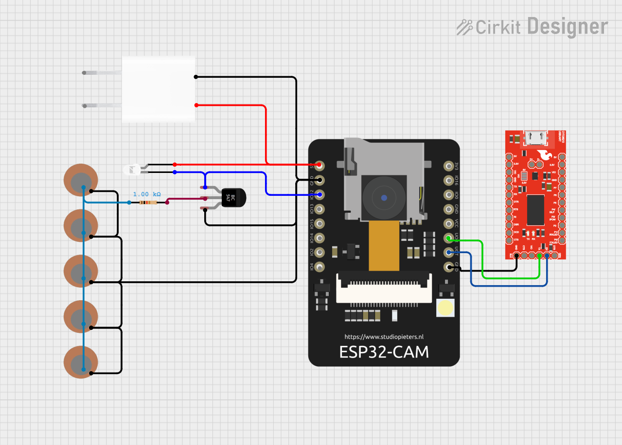
Circuit Documentation
Summary of the Circuit
This circuit appears to be designed for interfacing an ESP32 CAM module with a SparkFun USB UART Breakout board for serial communication, and it includes a BC547 transistor to control an LED. The circuit is powered by a 5V adapter. Additionally, there are multiple piezo sensors connected to the circuit, which are likely used for sensing vibrations or similar physical inputs. The piezo sensors are interfaced with the ESP32 CAM through a resistor and the BC547 transistor, which may be used to amplify the signal or to act as a switch.
Component List
ESP32 CAM
- Microcontroller module with camera support
- Pins: 5V, GND, GPIO12, GPIO13, GPIO15, GPIO14, GPIO2, GPIO4, 3.3V, GPIO16, GPIO0, 3.3V / 5V / P_OUT, GPIO3 / RX, GPIO1 / TX
SparkFun USB UART Breakout - CY7C65213
- USB to serial interface module
- Pins: D+, D-, CTS, DTR, GND, RXD, TXD, VCCIO, DCD, DSR, RI, RTS, 3.3V, 5V, GPIO0, GPIO1, GPIO2, GPIO3, GPIO4, GPIO5, GPIO6, GPIO7
BC547 Transistor
- NPN bipolar junction transistor
- Pins: Collector, Base, Emitter
LED: Two Pin (white)
- Standard white LED
- Pins: cathode, anode
Resistor
- Passive component used to limit current
- Resistance: 1000 Ohms
Piezo Sensor
- Sensor used to detect vibrations or pressure
- Pins: +, -
5V Adapter
- Power supply module
- Pins: AC In 1, AC In 2, 5V, GND
Wiring Details
ESP32 CAM
- 5V connected to the anode of the LED and 5V output of the 5V Adapter
- GND connected to the emitters of all Piezo Sensors, GND of the 5V Adapter, and GND of the SparkFun USB UART Breakout
- GPIO12 connected to the collector of the BC547 Transistor
- GPIO3 / RX connected to TXD of the SparkFun USB UART Breakout
- GPIO1 / TX connected to RXD of the SparkFun USB UART Breakout
SparkFun USB UART Breakout - CY7C65213
- TXD connected to GPIO3 / RX of the ESP32 CAM
- RXD connected to GPIO1 / TX of the ESP32 CAM
- GND connected to GND of the ESP32 CAM
BC547 Transistor
- Collector connected to the cathode of the LED and GPIO12 of the ESP32 CAM
- Base connected to pin2 of the Resistor
- Emitter connected to GND of the ESP32 CAM and the negative pins of all Piezo Sensors
LED: Two Pin (white)
- Anode connected to 5V of the ESP32 CAM and 5V output of the 5V Adapter
- Cathode connected to the collector of the BC547 Transistor
Resistor
- Pin1 connected to the positive pins of all Piezo Sensors
- Pin2 connected to the base of the BC547 Transistor
Piezo Sensors
- Positive pins connected to pin1 of the Resistor
- Negative pins connected to the emitter of the BC547 Transistor and GND of the ESP32 CAM
5V Adapter
- 5V output connected to the anode of the LED and 5V of the ESP32 CAM
- GND connected to the emitters of all Piezo Sensors and GND of the ESP32 CAM
Documented Code
No code has been provided for the microcontrollers in the circuit. Therefore, there is no code to document at this time. If code becomes available, it should be documented here with explanations of its functionality and how it interacts with the hardware components of the circuit.