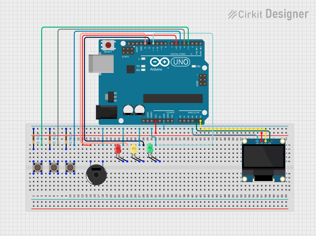
Arduino UNO Controlled Interactive LED and Buzzer System

Circuit Documentation
Summary of the Circuit
This circuit is designed around an Arduino UNO microcontroller and includes various components such as pushbuttons, resistors, LEDs, a piezo buzzer, and a 0.96" OLED display. The pushbuttons are used as input devices, the resistors are for current limiting and pull-down configurations, the LEDs serve as visual indicators, the piezo buzzer provides audio feedback, and the OLED display is used for visual output. The circuit is likely intended for a user interface application with visual and auditory feedback.
Component List
Arduino UNO
- Microcontroller board based on the ATmega328P
- It has 14 digital input/output pins, 6 analog inputs, a 16 MHz quartz crystal, a USB connection, a power jack, an ICSP header, and a reset button.
Resistor (200 Ohms)
- Passive two-terminal electrical component that implements electrical resistance as a circuit element.
- Used for current limiting and pull-down configurations.
Pushbutton
- A simple switch mechanism for controlling some aspect of a machine or a process.
- Buttons are typically made out of hard material, usually plastic or metal.
Piezo Buzzer
- An electronic device that produces a tone, buzz, or click when electricity is applied.
- Commonly used for sound alerts and alarms.
LED: Two Pin (red, green, yellow)
- Light Emitting Diode (LED) is a semiconductor light source that emits light when current flows through it.
- The color of the emitted light depends on the semiconductor material and can be red, green, or yellow.
0.96" OLED
- A small display screen made with organic light-emitting diode technology.
- Used for displaying text, images, and animations.
Wiring Details
Arduino UNO
- Digital Pins D3, D4, D5 are connected to the output pins of three separate pushbuttons.
- Digital Pins D6 is connected to the Piezo Buzzer.
- Digital Pins D11, D12, D13 are connected to the anodes of the green, yellow, and red LEDs respectively.
- Analog Pins A4, A5 are connected to the SDA and SCK pins of the OLED display.
- The 3.3V pin is connected to the VDD pin of the OLED display.
- The GND pin is connected to the common ground net, which includes the cathodes of all LEDs, one pin of the Piezo Buzzer, and the GND pin of the OLED display.
Resistor (200 Ohms)
- Each resistor is connected between the ground and one of the pushbutton input pins, serving as a pull-down resistor.
Pushbutton
- Each pushbutton has one input pin connected to a 200 Ohm resistor and ground, and one output pin connected to an Arduino UNO digital input pin.
Piezo Buzzer
- One pin is connected to the Arduino UNO digital pin D6, and the other pin is connected to the common ground net.
LED: Two Pin (red, green, yellow)
- The cathode of each LED is connected to the common ground net.
- The anode of each LED is connected to a separate Arduino UNO digital output pin (D11, D12, D13).
0.96" OLED
- The SDA and SCK pins are connected to the Arduino UNO analog pins A4 and A5.
- The VDD pin is connected to the Arduino UNO 3.3V pin.
- The GND pin is connected to the common ground net.
Documented Code
void setup() {
  // put your setup code here, to run once:

}

void loop() {
  // put your main code here, to run repeatedly:

}
The provided code is a template with empty setup() and loop() functions. The setup() function is intended for initialization code that runs once when the program starts, such as configuring pin modes. The loop() function contains the main logic of the program, which runs continuously after the setup() function completes. Additional code is required to control the components based on the wiring details provided.