
Arduino Mega 2560 and BTS7960 Motor Driver Controlled High RPM DC Motor System
View and Edit Project In Cirkit Designer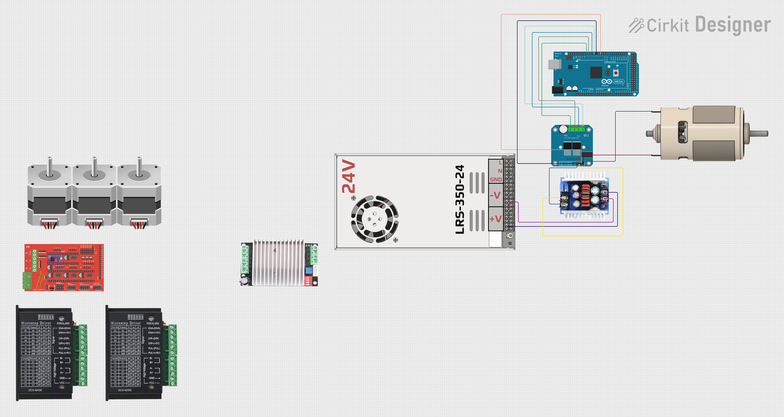
Circuit Documentation
Summary
This circuit involves an Arduino Mega 2560 microcontroller interfacing with a BTS7960 motor driver to control an RS 775 DC motor. The circuit also includes a MW LRS-350-24 power supply and a Step Down Buck converter to provide the necessary voltage levels. The Arduino Mega 2560 is programmed to control the motor driver via PWM signals.
Component List
TB6600
- Description: Stepper motor driver
- Pins: ENA-, ENA+, DIR-, DIR+, PUL-, PUL+, B-, B+, A-, A+, GND, VCC
Arduino Mega 2560
- Description: Microcontroller board
- Pins: IOREF, RESET, 3V3, 5V, GND, VIN, A0-A15, D0-D53, AREF, SDA, SCL
RAMPS1.4
- Description: RepRap Arduino Mega Pololu Shield
- Pins: 2B, 2A, 1A, 1B, S, GND, VCC, SDA, SCL, 12V5A, 12V11A, THERM0-THERM2, 5V, D11, D6, D5, D4, D1, D2, A3, A4, A9, D40, D42, A11, A5, A10, D44, A12, D52, D50, D53, D51, D49, D32, D47, D45, D43, D41, D39, D37, D35, D33, D31, D29, D27, D25, D23, D17, D16, PS-ON, MS1, MS2, MS3, Vmot, VDD, DIR, STEP, SLP, RESET, ENABLE, 12V
MW LRS-350-24
- Description: 24V power supply
- Pins: +24V Output, -24V Output, GND, N, L
NEMA23
- Description: Stepper motor
- Pins: D, B, C, A
BTS7960 Motor Driver
- Description: High-power motor driver
- Pins: Pin 1-12
Step Down Buck converter
- Description: Voltage regulator
- Pins: IN+, IN-, OUT-, OUT+
RS 775 DC MOTOR
- Description: DC motor
- Pins: V+, V-
Wiring Details
TB6600
- ENA-: Not connected
- ENA+: Not connected
- DIR-: Not connected
- DIR+: Not connected
- PUL-: Not connected
- PUL+: Not connected
- B-: Not connected
- B+: Not connected
- A-: Not connected
- A+: Not connected
- GND: Not connected
- VCC: Not connected
Arduino Mega 2560
- D3 PWM: Connected to Pin 7 on BTS7960 Motor Driver
- D5 PWM: Connected to Pin 8 on BTS7960 Motor Driver
- D6 PWM: Connected to Pin 9 on BTS7960 Motor Driver
- D7 PWM: Connected to Pin 10 on BTS7960 Motor Driver
- D8 PWM: Connected to Pin 11 on BTS7960 Motor Driver
- D9 PWM: Connected to Pin 12 on BTS7960 Motor Driver
RAMPS1.4
- Not connected in this circuit
MW LRS-350-24
- +24V Output: Connected to IN+ on Step Down Buck converter
- -24V Output: Connected to IN- on Step Down Buck converter
- GND: Not connected
- N: Not connected
- L: Not connected
NEMA23
- Not connected in this circuit
BTS7960 Motor Driver
- Pin 1: Connected to OUT+ on Step Down Buck converter
- Pin 2: Connected to OUT- on Step Down Buck converter
- Pin 3: Connected to V+ on RS 775 DC MOTOR
- Pin 4: Connected to V- on RS 775 DC MOTOR
- Pin 7: Connected to D3 PWM on Arduino Mega 2560
- Pin 8: Connected to D5 PWM on Arduino Mega 2560
- Pin 9: Connected to D6 PWM on Arduino Mega 2560
- Pin 10: Connected to D7 PWM on Arduino Mega 2560
- Pin 11: Connected to D8 PWM on Arduino Mega 2560
- Pin 12: Connected to D9 PWM on Arduino Mega 2560
Step Down Buck converter
- IN+: Connected to +24V Output on MW LRS-350-24
- IN-: Connected to -24V Output on MW LRS-350-24
- OUT+: Connected to Pin 1 on BTS7960 Motor Driver
- OUT-: Connected to Pin 2 on BTS7960 Motor Driver
RS 775 DC MOTOR
- V+: Connected to Pin 3 on BTS7960 Motor Driver
- V-: Connected to Pin 4 on BTS7960 Motor Driver
Documented Code
// Define the PWM pins connected to the BTS7960 Motor Driver
const int pwmPin1 = 3; // Connected to Pin 7 on BTS7960
const int pwmPin2 = 5; // Connected to Pin 8 on BTS7960
const int pwmPin3 = 6; // Connected to Pin 9 on BTS7960
const int pwmPin4 = 7; // Connected to Pin 10 on BTS7960
const int pwmPin5 = 8; // Connected to Pin 11 on BTS7960
const int pwmPin6 = 9; // Connected to Pin 12 on BTS7960

void setup() {
  // Set PWM pins as output
  pinMode(pwmPin1, OUTPUT);
  pinMode(pwmPin2, OUTPUT);
  pinMode(pwmPin3, OUTPUT);
  pinMode(pwmPin4, OUTPUT);
  pinMode(pwmPin5, OUTPUT);
  pinMode(pwmPin6, OUTPUT);

  // Set all PWM pins to maximum value (255) for high RPM
  analogWrite(pwmPin1, 255);
  analogWrite(pwmPin2, 255);
  analogWrite(pwmPin3, 255);
  analogWrite(pwmPin4, 255);
  analogWrite(pwmPin5, 255);
  analogWrite(pwmPin6, 255);
}

void loop() {
  // No need to do anything in the loop, motor runs continuously at high RPM
}