
Arduino UNO-Based Battery-Powered DC Motor Control System with Rocker Switches
View and Edit Project In Cirkit Designer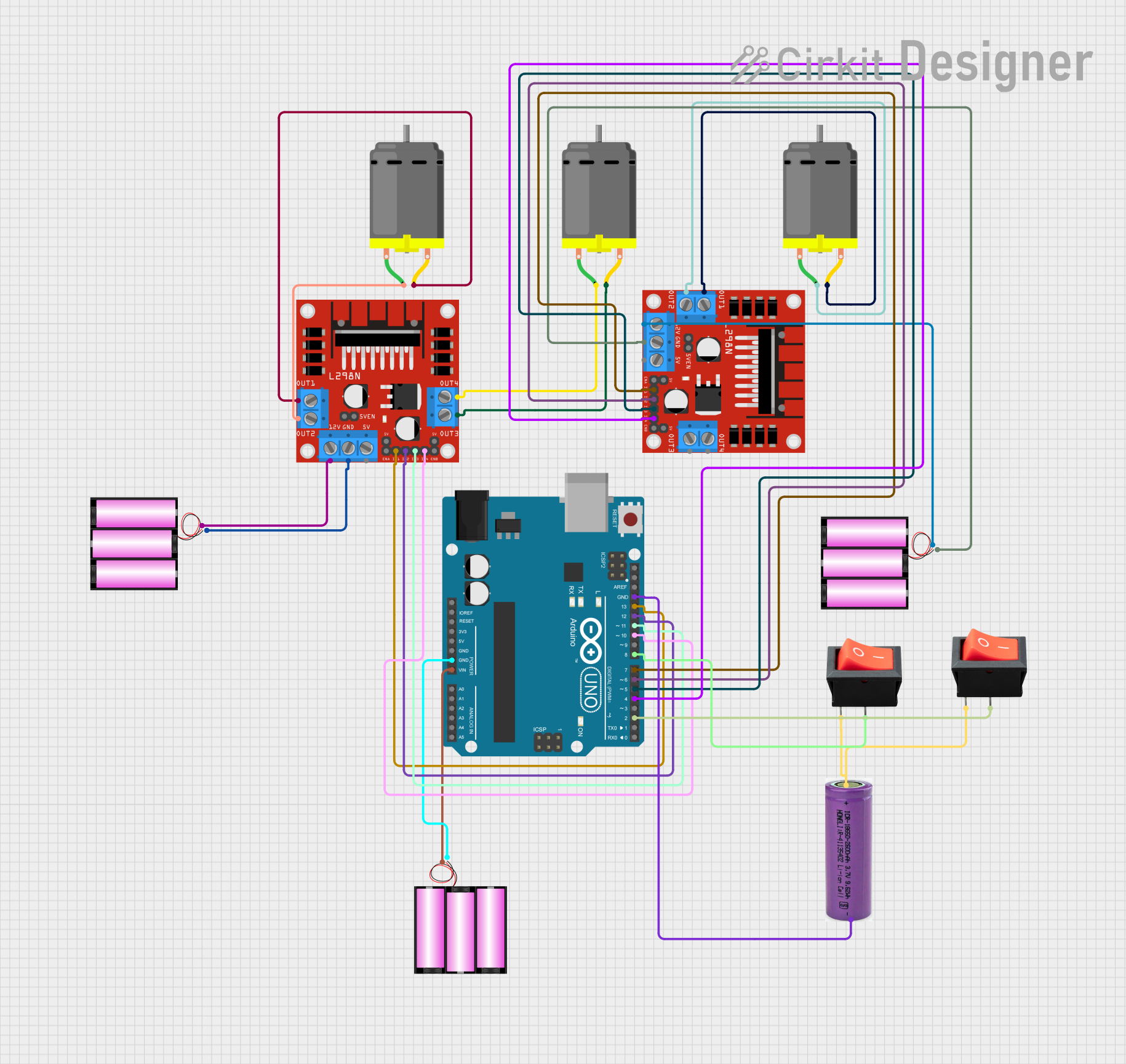
Circuit Documentation
Summary
This circuit is designed to control multiple DC motors using an Arduino UNO and two L298N motor drivers. The circuit also includes rocker switches for direction control and emergency stop functionality. The power supply is provided by multiple 12V batteries and a 3.3V battery.
Component List
Arduino UNO
- Description: Microcontroller board based on the ATmega328P.
- Pins: UNUSED, IOREF, Reset, 3.3V, 5V, GND, Vin, A0, A1, A2, A3, A4, A5, SCL, SDA, AREF, D13, D12, D11, D10, D9, D8, D7, D6, D5, D4, D3, D2, D1, D0
DC Motor
- Description: Standard DC motor.
- Pins: pin 1, pin 2
L298N DC Motor Driver
- Description: Dual H-Bridge motor driver.
- Pins: OUT1, OUT2, 12V, GND, 5V, OUT3, OUT4, 5V-ENA-JMP-I, 5V-ENA-JMP-O, +5V-J1, +5V-J2, ENA, IN1, IN2, IN3, IN4, ENB
Battery 12V
- Description: 12V battery for powering motors and motor drivers.
- Pins: +, -
3.3V Battery
- Description: 3.3V battery for powering switches.
- Pins: +, -
Rocker Switch
- Description: Switch for direction control and emergency stop.
- Pins: output, input
Wiring Details
Arduino UNO
- GND connected to - of 12V Battery
- Vin connected to + of 12V Battery
- GND connected to - of 3.3V Battery
- D13 connected to IN1 of L298N Motor Driver 1
- D12 connected to IN2 of L298N Motor Driver 1
- D11 connected to IN3 of L298N Motor Driver 1
- D10 connected to IN4 of L298N Motor Driver 1
- D8 connected to output of Rocker Switch 1
- D7 connected to IN1 of L298N Motor Driver 2
- D6 connected to IN2 of L298N Motor Driver 2
- D5 connected to IN3 of L298N Motor Driver 2
- D4 connected to IN4 of L298N Motor Driver 2
- D2 connected to output of Rocker Switch 2
DC Motor 1
- pin 1 connected to OUT4 of L298N Motor Driver 1
- pin 2 connected to OUT3 of L298N Motor Driver 1
DC Motor 2
- pin 1 connected to OUT2 of L298N Motor Driver 1
- pin 2 connected to OUT1 of L298N Motor Driver 1
DC Motor 3
- pin 1 connected to OUT2 of L298N Motor Driver 2
- pin 2 connected to OUT1 of L298N Motor Driver 2
L298N Motor Driver 1
- 12V connected to + of 12V Battery
- GND connected to - of 12V Battery
L298N Motor Driver 2
- 12V connected to + of 12V Battery
- GND connected to - of 12V Battery
Rocker Switch 1
- input connected to + of 3.3V Battery
- output connected to D8 of Arduino UNO
Rocker Switch 2
- input connected to + of 3.3V Battery
- output connected to D2 of Arduino UNO
Code Documentation
// Motor driver 1 pins
const int IN1_1 = 13;
const int IN2_1 = 12;
const int IN3_1 = 11;
const int IN4_1 = 10;

// Motor driver 2 pins
const int IN1_2 = 7;
const int IN2_2 = 6;
const int IN3_2 = 5;
const int IN4_2 = 4;

// ESP32-CAM pins
const int VOR = 0;
const int VOT = 1;

// Rocker switch pins
const int DIRECTION_SWITCH = 2;
const int EMERGENCY_STOP_SWITCH = 8;

void setup() {
  // Initialize motor driver 1 pins
  pinMode(IN1_1, OUTPUT);
  pinMode(IN2_1, OUTPUT);
  pinMode(IN3_1, OUTPUT);
  pinMode(IN4_1, OUTPUT);

  // Initialize motor driver 2 pins
  pinMode(IN1_2, OUTPUT);
  pinMode(IN2_2, OUTPUT);
  pinMode(IN3_2, OUTPUT);
  pinMode(IN4_2, OUTPUT);

  // Initialize ESP32-CAM pins
  pinMode(VOR, INPUT);
  pinMode(VOT, OUTPUT);

  // Initialize rocker switch pins
  pinMode(DIRECTION_SWITCH, INPUT);
  pinMode(EMERGENCY_STOP_SWITCH, INPUT);

  // Initial motor states
  stopMotors();
}

void loop() {
  // Read switch states
  int directionSwitchState = digitalRead(DIRECTION_SWITCH);
  int emergencyStopSwitchState = digitalRead(EMERGENCY_STOP_SWITCH);

  // Control motors based on switch states
  if (emergencyStopSwitchState == HIGH) {
    // Emergency stop: Stop all motors
    stopMotors();
  } else {
    if (directionSwitchState == HIGH) {
      // Move motors forward
      moveForward();
    } else {
      // Move motors backward
      moveBackward();
    }
  }

  delay(100); // Small delay for switch debounce
}

void stopMotors() {
  // Stop motor driver 1
  digitalWrite(IN1_1, LOW);
  digitalWrite(IN2_1, LOW);
  digitalWrite(IN3_1, LOW);
  digitalWrite(IN4_1, LOW);

  // Stop motor driver 2
  digitalWrite(IN1_2, LOW);
  digitalWrite(IN2_2, LOW);
  digitalWrite(IN3_2, LOW);
  digitalWrite(IN4_2, LOW);
}

void moveForward() {
  // Motor driver 1: Forward
  digitalWrite(IN1_1, HIGH);
  digitalWrite(IN2_1, LOW);
  digitalWrite(IN3_1, HIGH);
  digitalWrite(IN4_1, LOW);

  // Motor driver 2: Forward
  digitalWrite(IN1_2, HIGH);
  digitalWrite(IN2_2, LOW);
  digitalWrite(IN3_2, HIGH);
  digitalWrite(IN4_2, LOW);
}

void moveBackward() {
  // Motor driver 1: Backward
  digitalWrite(IN1_1, LOW);
  digitalWrite(IN2_1, HIGH);
  digitalWrite(IN3_1, LOW);
  digitalWrite(IN4_1, HIGH);

  // Motor driver 2: Backward
  digitalWrite(IN1_2, LOW);
  digitalWrite(IN2_2, HIGH);
  digitalWrite(IN3_2, LOW);
  digitalWrite(IN4_2, HIGH);
}
This code initializes the pins for the motor drivers and rocker switches, reads the state of the switches, and controls the motors accordingly. The stopMotors, moveForward, and moveBackward functions handle the motor control logic.