
Raspberry Pi Zero-Based Smart Home Automation System with Current Sensing and Motion Detection
View and Edit Project In Cirkit Designer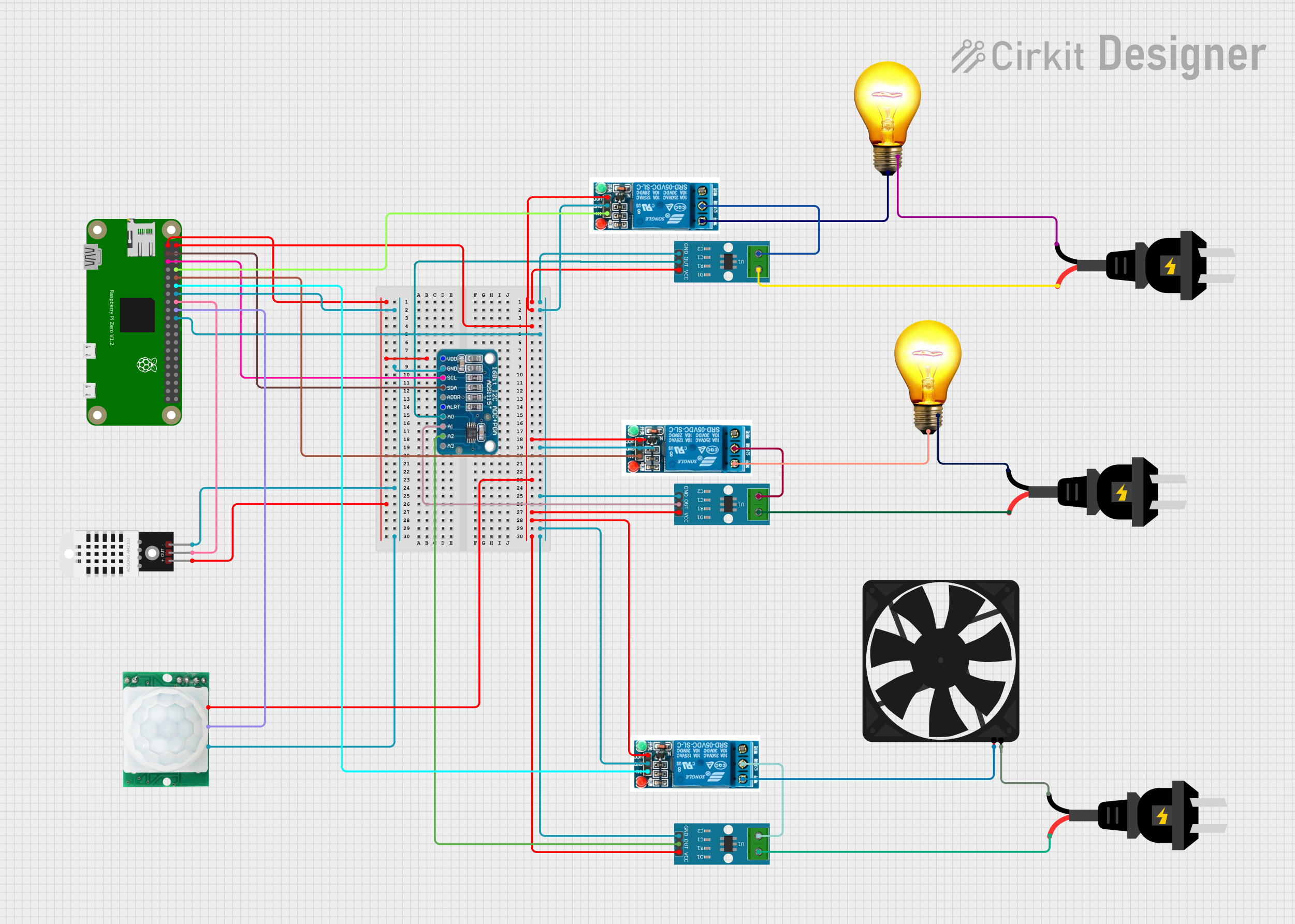
Circuit Documentation
Summary
This circuit is designed to interface a Raspberry Pi Zero with various sensors and actuators. The Raspberry Pi Zero serves as the central controller, interfacing with current sensors, relays, a motion sensor, a temperature and humidity sensor, and an analog-to-digital converter (ADC). The circuit is powered by both 3.3V and 5V sources from the Raspberry Pi Zero, and it controls AC loads such as bulbs and a fan through relays.
Component List
Raspberry Pi Zero
- Description: A small, affordable computer that can be used for a variety of electronics projects.
- Pins: 5V, 3.3V, GPIO2 (SDA), GND, GPIO3 (SCL), GPIO14, GPIO4, GPIO15, GPIO18, GPIO17, GPIO27, GPIO23, GPIO22, GPIO24, GPIO10, GPIO25, GPIO9, GPIO8, GPIO11, GPIO7, ID_SC, ID_SD, GPIO5, GPIO12, GPIO6, GPIO13, GPIO16, GPIO19, GPIO20, GPIO26, GPIO21
ACS712 Current Sensor 5A 20A 30A
- Description: A current sensor that provides an analog voltage output proportional to the current passing through it.
- Pins: 1, 2, GND, OUT, VCC
5V Relay
- Description: An electromechanical switch used to control high voltage devices with a low voltage signal.
- Pins: Normally Open, Common terminal, Normally Closed, In, GND, VCC
AC Bulb
- Description: A standard AC-powered light bulb.
- Pins: P, N
Fan
- Description: A DC-powered fan.
- Pins: GND, 5V
AC Source
- Description: An AC power source.
- Pins: +, -
ADS1115
- Description: A 16-bit analog-to-digital converter (ADC) with I2C interface.
- Pins: VDD, GND, SCL, SDA, ADDR, ALRT, A0, A1, A2, A3
DHT22
- Description: A temperature and humidity sensor.
- Pins: +, Out, -
HC-SR501 Motion Sensor
- Description: A motion sensor that detects movement using passive infrared (PIR) technology.
- Pins: GND, OUT, VCC
Wiring Details
Raspberry Pi Zero
- 3.3V connected to VDD of ADS1115 and + of DHT22.
- 5V connected to VCC of all ACS712 Current Sensors, all 5V Relays, and HC-SR501 Motion Sensor.
- GND connected to GND of all ACS712 Current Sensors, all 5V Relays, ADS1115, DHT22, and HC-SR501 Motion Sensor.
- GPIO2 (SDA) connected to SDA of ADS1115.
- GPIO3 (SCL) connected to SCL of ADS1115.
- GPIO14 connected to In of the first 5V Relay.
- GPIO15 connected to In of the second 5V Relay.
- GPIO18 connected to In of the third 5V Relay.
- GPIO23 connected to Out of DHT22.
- GPIO24 connected to OUT of HC-SR501 Motion Sensor.
ACS712 Current Sensor 5A 20A 30A
- VCC connected to 5V of Raspberry Pi Zero.
- GND connected to GND of Raspberry Pi Zero.
- 1 of the first sensor connected to + of the first AC Source.
- 2 of the first sensor connected to Common terminal of the first 5V Relay.
- OUT of the first sensor connected to A0 of ADS1115.
- 1 of the second sensor connected to + of the second AC Source.
- 2 of the second sensor connected to Common terminal of the second 5V Relay.
- OUT of the second sensor connected to A1 of ADS1115.
- 1 of the third sensor connected to + of the third AC Source.
- 2 of the third sensor connected to Common terminal of the third 5V Relay.
- OUT of the third sensor connected to A2 of ADS1115.
5V Relay
- VCC connected to 5V of Raspberry Pi Zero.
- GND connected to GND of Raspberry Pi Zero.
- In of the first relay connected to GPIO14 of Raspberry Pi Zero.
- In of the second relay connected to GPIO15 of Raspberry Pi Zero.
- In of the third relay connected to GPIO18 of Raspberry Pi Zero.
- Common terminal of the first relay connected to 2 of the first ACS712 Current Sensor.
- Common terminal of the second relay connected to 2 of the second ACS712 Current Sensor.
- Common terminal of the third relay connected to 2 of the third ACS712 Current Sensor.
- Normally Open of the first relay connected to P of the first AC Bulb.
- Normally Open of the second relay connected to P of the second AC Bulb.
- Normally Open of the third relay connected to 5V of the Fan.
AC Bulb
- P of the first bulb connected to Normally Open of the first 5V Relay.
- N of the first bulb connected to - of the first AC Source.
- P of the second bulb connected to Normally Open of the second 5V Relay.
- N of the second bulb connected to - of the second AC Source.
Fan
- 5V connected to Normally Open of the third 5V Relay.
- GND connected to - of the third AC Source.
AC Source
- + of the first source connected to 1 of the first ACS712 Current Sensor.
- - of the first source connected to N of the first AC Bulb.
- + of the second source connected to 1 of the second ACS712 Current Sensor.
- - of the second source connected to N of the second AC Bulb.
- + of the third source connected to 1 of the third ACS712 Current Sensor.
- - of the third source connected to GND of the Fan.
ADS1115
- VDD connected to 3.3V of Raspberry Pi Zero.
- GND connected to GND of Raspberry Pi Zero.
- SCL connected to GPIO3 (SCL) of Raspberry Pi Zero.
- SDA connected to GPIO2 (SDA) of Raspberry Pi Zero.
- A0 connected to OUT of the first ACS712 Current Sensor.
- A1 connected to OUT of the second ACS712 Current Sensor.
- A2 connected to OUT of the third ACS712 Current Sensor.
DHT22
- + connected to 3.3V of Raspberry Pi Zero.
- Out connected to GPIO23 of Raspberry Pi Zero.
- - connected to GND of Raspberry Pi Zero.
HC-SR501 Motion Sensor
- VCC connected to 5V of Raspberry Pi Zero.
- OUT connected to GPIO24 of Raspberry Pi Zero.
- GND connected to GND of Raspberry Pi Zero.
Code
No code is provided for this circuit.