
ESP32-Controlled Brushless Motor with Magnetic Sensing and LED Display
View and Edit Project In Cirkit Designer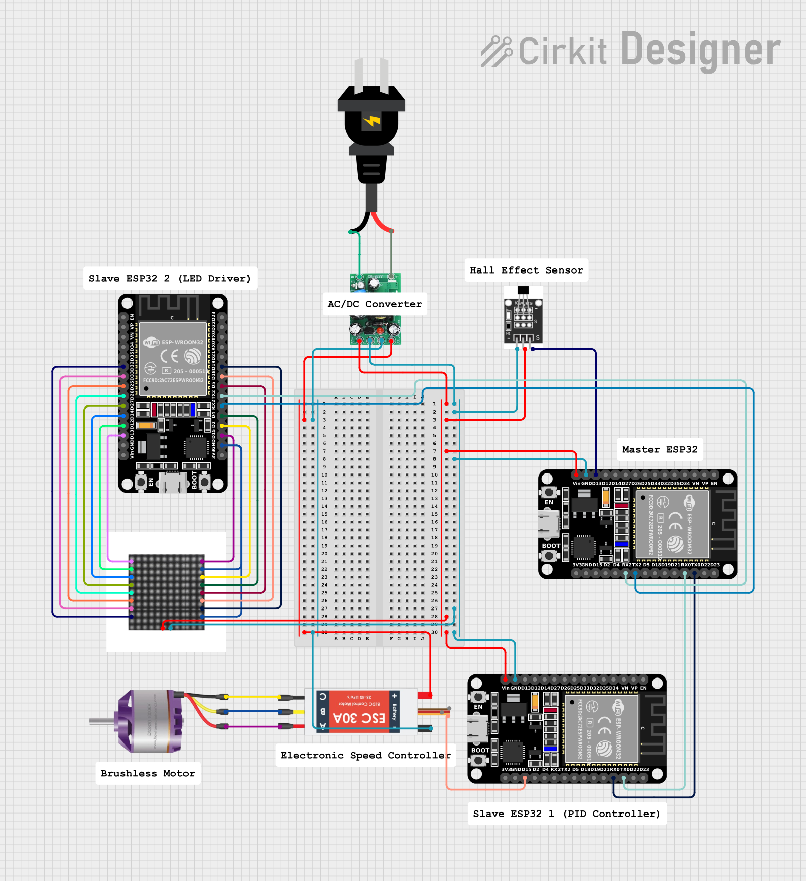
Circuit Documentation
Summary
The circuit in question appears to be a complex system involving multiple ESP32 microcontrollers, a Hall sensor, an AC to DC converter (actodc), an AC power source, a brushless motor with an Electronic Speed Controller (ESC), and a 64x64 LED matrix display. The ESP32 microcontrollers are responsible for controlling the various components and handling sensor input. The Hall sensor is likely used for detecting magnetic fields, which could be part of a positioning or speed detection system. The brushless motor is driven by the ESC, which receives its power from the actodc, converting AC power to the required DC voltages. The LED matrix is controlled by one of the ESP32s for display purposes.
Component List
- ESP32 (30 pin): A microcontroller with WiFi and Bluetooth capabilities, featuring a wide range of GPIO pins for interfacing with various sensors and peripherals.
- Hall Sensor: A transducer that varies its output voltage in response to a magnetic field.
- AC to DC Converter (actodc): A power supply module that converts AC input to 5V and 12V DC outputs.
- AC Source: The primary power source for the circuit, providing alternating current.
- Brushless Motor: A type of electric motor that uses electronic commutation instead of mechanical means to change the current direction.
- Electronic Speed Controller (ESC): An electronic circuit that controls and regulates the speed of an electric motor.
- 64x64 LED Matrix: A large display composed of LEDs arranged in a matrix format, capable of displaying various patterns and information.
Wiring Details
ESP32 (30 pin)
- EN, VP, VN, D34, D35, D32, D33, D25, D26, D27, D14, D12, D13, TX0, RX0, D21, D19, D18, D5, TX2, RX2, D4, D2, D15, 3V3: Various GPIO pins used for interfacing with sensors, communication, and control signals.
- GND: Connected to the ground of the circuit.
- Vin: Connected to the 5V output from the actodc, powering the microcontroller.
Hall Sensor
- -: Connected to the ground of the circuit.
- +: Connected to the 5V output from the actodc, powering the sensor.
- S: Signal output connected to the D13 pin of one of the ESP32 microcontrollers.
AC to DC Converter (actodc)
- 12v: 12V DC output, connected to the Battery VCC of the ESC.
- -: Ground output, connected to various components including the Hall Sensor, ESP32s, and the ESC.
- 5v: 5V DC output, connected to the Hall Sensor, ESP32s, and the LED Matrix.
- live: AC input connected to the negative terminal of the AC source.
- neutral: AC input connected to the positive terminal of the AC source.
AC Source
- -: Connected to the live input of the actodc.
- +: Connected to the neutral input of the actodc.
Brushless Motor
- L1, L2, L3: Motor leads connected to the corresponding M1, M2, M3 outputs of the ESC.
Electronic Speed Controller (ESC)
- Battery VCC: Connected to the 12V output of the actodc.
- Battery GND: Connected to the ground of the actodc.
- Signal: Control signal input from the D15 pin of one of the ESP32 microcontrollers.
- 5v out, GND out: Power outputs, not detailed in the provided connections.
- M1, M2, M3: Outputs connected to the corresponding L1, L2, L3 inputs of the Brushless Motor.
64x64 LED Matrix
- R1, B1, R2, B2, A, Clk, OE, G1, GND, G2, E, B, D/GND, Lat, C, +5V: Various control and power inputs connected to corresponding GPIO pins on one of the ESP32 microcontrollers.
Documented Code
ESP32 Microcontroller Code (Instance 1)
void setup() {
  // put your setup code here, to run once:

}

void loop() {
  // put your main code here, to run repeatedly:

}
ESP32 Microcontroller Code (Instance 2)
void setup() {
  // put your setup code here, to run once:

}

void loop() {
  // put your main code here, to run repeatedly:

}
Note: The provided code for both ESP32 instances is a template with no specific functionality. The actual application code needs to be developed based on the requirements of the circuit's operation.