
Arduino Mega-Controlled Robotics Interface with Ultrasonic Sensing and Motor Management
View and Edit Project In Cirkit Designer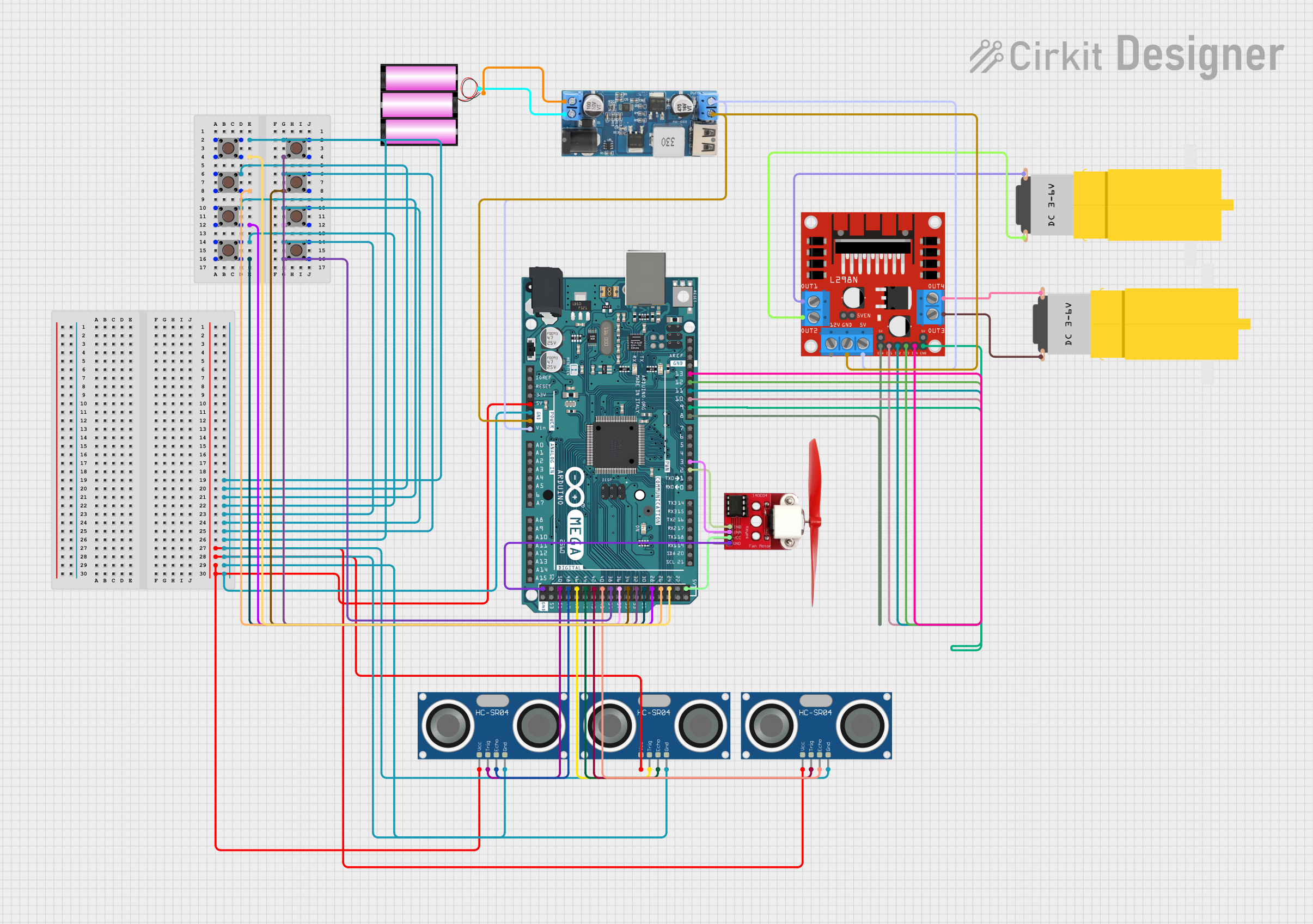
Circuit Documentation
Summary
The circuit in question is designed to interface multiple pushbuttons, ultrasonic sensors, a DC motor driver, motors, a fan motor, and a power converter with an Arduino Mega 2560 microcontroller. The circuit appears to be a control system, possibly for a robotic application, given the presence of sensors and motor drivers. The pushbuttons may serve as user inputs, the ultrasonic sensors could be used for distance measurement, and the motors indicate actuation mechanisms. The fan motor suggests a need for cooling, possibly for the motors or the system as a whole. The power converter is used to step down the voltage from a 12V battery to 5V required by some components.
Component List
Pushbuttons
- Description: Momentary tactile pushbuttons, typically used for user input.
- Pins: Pin 1 (in), Pin 2 (in), Pin 3 (out), Pin 4 (out).
HC-SR04 Ultrasonic Sensors
- Description: Ultrasonic distance sensors, used for measuring distances via ultrasonic waves.
- Pins: VCC, TRIG, ECHO, GND.
L298N DC Motor Driver
- Description: A motor driver module capable of driving a couple of DC motors or a stepper motor.
- Pins: OUT1, OUT2, 12V, GND, 5V, OUT3, OUT4, ENA, IN1, IN2, IN3, IN4, ENB.
Arduino Mega 2560
- Description: A microcontroller board based on the ATmega2560, with numerous digital and analog I/O pins.
- Pins: Various digital I/O and power pins.
Motors (Amarillo Motorreductor Hobby)
- Description: Yellow geared DC motors, typically used in hobby robotics.
- Pins: VCC, GND.
12V to 5V Step Down Power Converter
- Description: A voltage converter that steps down input voltage from 12V to a stable 5V output.
- Pins: VIN 9v-36v, VIN+, VIN-, USB OUTPUT 5V, 5v OUTPUT, GND.
12V Battery
- Description: A power source for the circuit.
- Pins: +, -.
Fan Motor (L9110)
- Description: A small DC fan motor, possibly used for cooling.
- Pins: INB, INA, VCC, GND.
Wiring Details
Pushbuttons
- Connected to various digital I/O pins on the Arduino Mega 2560 for input detection.
HC-SR04 Ultrasonic Sensors
- VCC pins connected to the 5V output from the Arduino Mega 2560.
- GND pins connected to the GND on the Arduino Mega 2560.
- TRIG and ECHO pins connected to specific digital I/O pins on the Arduino Mega 2560 for triggering and receiving ultrasonic signals.
L298N DC Motor Driver
- OUT1, OUT2, OUT3, and OUT4 connected to the motors.
- 12V and GND pins for power input, possibly from the 12V battery.
- 5V pin connected to the 5V output from the step-down converter.
- ENA, ENB, IN1, IN2, IN3, and IN4 connected to specific PWM-capable digital I/O pins on the Arduino Mega 2560 for motor control.
Motors (Amarillo Motorreductor Hobby)
- Connected to the OUT pins of the L298N DC motor driver for operation.
12V to 5V Step Down Power Converter
- VIN+ and VIN- connected to the 12V battery.
- 5V OUTPUT connected to the 5V input on the L298N DC motor driver and possibly other 5V components.
12V Battery
- Provides power to the step-down converter and possibly directly to the motor driver.
Fan Motor (L9110)
- VCC and GND connected to the 5V and GND pins on the Arduino Mega 2560.
- INB and INA connected to specific PWM-capable digital I/O pins on the Arduino Mega 2560 for fan speed control.
Documented Code
Arduino Mega 2560 Code (sketch.ino)
void setup() {
  // put your setup code here, to run once:

}

void loop() {
  // put your main code here, to run repeatedly:

}
Note: The provided code is a template and does not contain any specific logic for the circuit's operation. The user is expected to fill in the setup and loop functions with code to initialize the pins and implement the desired functionality, such as reading button states, controlling the ultrasonic sensors, driving the motors, and managing the fan motor.