
Circuit Documentation
Summary
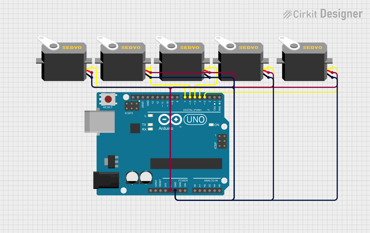
This circuit consists of an Arduino UNO microcontroller connected to five servo motors. The Arduino UNO provides power and control signals to the servos, allowing them to operate as intended. The servos are connected to the Arduino's digital pins for pulse control, and they share common power and ground connections.
Component List
Servo Motor
- Description: A servo motor is a rotary actuator that allows for precise control of angular position.
- Pins:
gnd,vcc,pulse - Purpose in Circuit: To provide controlled rotational movement.
Arduino UNO
- Description: A microcontroller board based on the ATmega328P.
- Pins:
UNUSED,IOREF,Reset,3.3V,5V,GND,Vin,A0,A1,A2,A3,A4,A5,SCL,SDA,AREF,D13,D12,D11,D10,D9,D8,D7,D6,D5,D4,D3,D2,D1,D0 - Purpose in Circuit: To control the servo motors by providing pulse-width modulation (PWM) signals.
Wiring Details
Servo Motor 1
- Pins:
gndconnected to Arduino UNOGNDvccconnected to Arduino UNO5Vpulseconnected to Arduino UNOD7
Servo Motor 2
- Pins:
gndconnected to Arduino UNOGNDvccconnected to Arduino UNO5Vpulseconnected to Arduino UNOD6
Servo Motor 3
- Pins:
gndconnected to Arduino UNOGNDvccconnected to Arduino UNO5Vpulseconnected to Arduino UNOD5
Servo Motor 4
- Pins:
gndconnected to Arduino UNOGNDvccconnected to Arduino UNO5Vpulseconnected to Arduino UNOD4
Servo Motor 5
- Pins:
gndconnected to Arduino UNOGNDvccconnected to Arduino UNO5Vpulseconnected to Arduino UNOD3
Documented Code
Arduino UNO Code
void setup() {
  // put your setup code here, to run once:

}

void loop() {
  // put your main code here, to run repeatedly:

}
This code is a basic template for the Arduino UNO. The setup() function is where you initialize your servos and other components, and the loop() function is where you write the main logic to control the servos.
Additional Documentation
This section is reserved for any additional documentation or notes that may be required for understanding the circuit and its operation.