Cirkit Designer
Your all-in-one circuit design IDE
Home /
Project Documentation
Arduino Nano Controlled Joystick with NRF24L01 Wireless Communication

Circuit Documentation
Summary
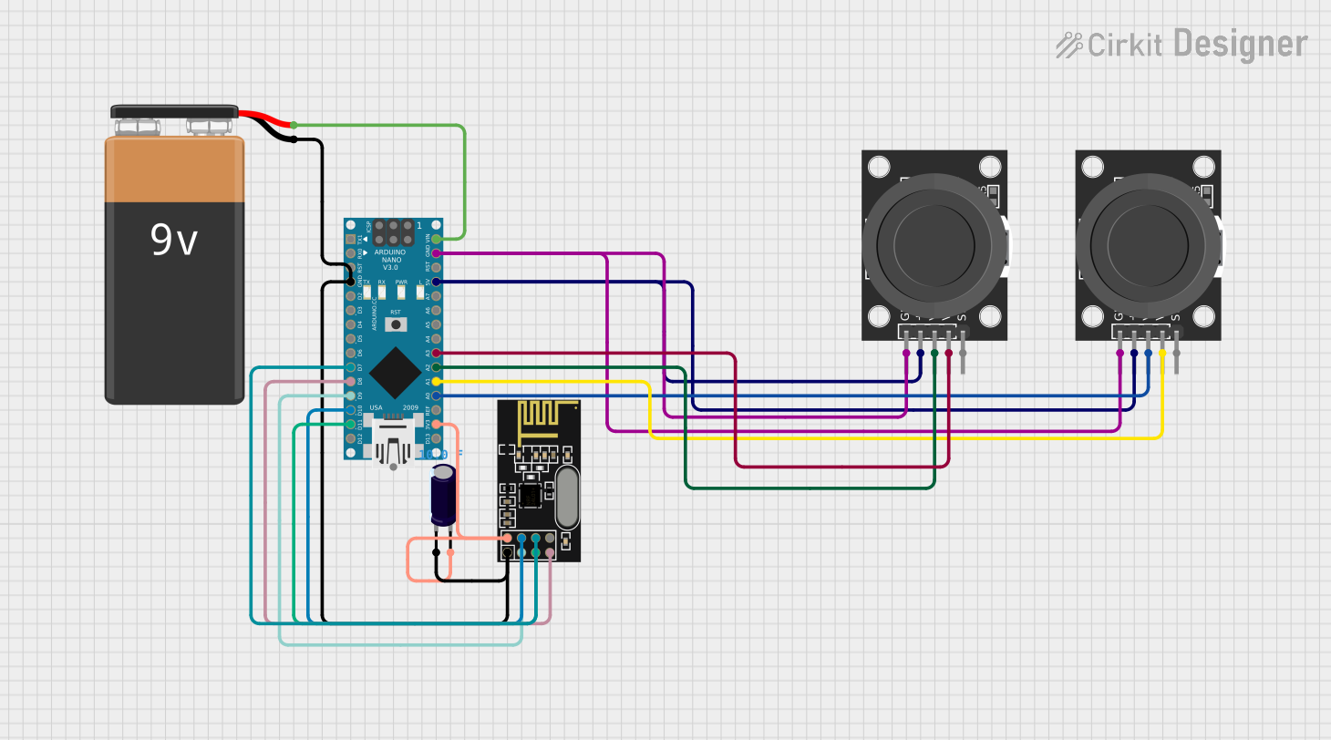
This circuit integrates an Arduino Nano microcontroller with a KY-023 Dual Axis Joystick Module, an NRF24L01 wireless transceiver module, an electrolytic capacitor, and a 9V battery. The Arduino Nano reads the joystick's position and button state, then transmits this information wirelessly via the NRF24L01 module. The electrolytic capacitor is used to stabilize the power supply to the NRF24L01, which is sensitive to power fluctuations. The 9V battery provides the power source for the circuit.
Component List
Arduino Nano
- Microcontroller board based on the ATmega328P
- It has a variety of digital and analog I/O pins.
KY-023 Dual Axis Joystick Module (x2)
- Provides 2-axis analog input and a push button.
- Operates at +5V.
NRF24L01
- A 2.4GHz wireless transceiver module.
- Communicates with the Arduino via SPI.
Electrolytic Capacitor
- Capacitance: 10 Farads
- Used for power supply decoupling.
9V Battery
- Provides power to the circuit.
Wiring Details
Arduino Nano
GNDconnected to the ground plane.D7connected to NRF24L01MOSI.D8connected to NRF24L01MISO.D9connected to NRF24L01CE.D10connected to NRF24L01CSN.D11/MOSIconnected to NRF24L01SCK.VINconnected to 9V Battery+.5Vconnected to both KY-023 Joystick Modules+5V.A3connected to one KY-023 Joystick ModuleVRy.A2connected to one KY-023 Joystick ModuleVRx.A1connected to the other KY-023 Joystick ModuleVRy.A0connected to the other KY-023 Joystick ModuleVRx.3V3connected to Electrolytic Capacitor+and NRF24L01VCC (3V).
KY-023 Dual Axis Joystick Module
GNDconnected to the ground plane.+5Vconnected to Arduino Nano5V.VRxconnected to Arduino NanoA0orA2.VRyconnected to Arduino NanoA1orA3.SW(not wired in this circuit).
NRF24L01
GNDconnected to the ground plane.MOSIconnected to Arduino NanoD7.CSNconnected to Arduino NanoD10.VCC (3V)connected to Electrolytic Capacitor+and Arduino Nano3V3.CEconnected to Arduino NanoD9.SCKconnected to Arduino NanoD11/MOSI.MISOconnected to Arduino NanoD8.
Electrolytic Capacitor
-connected to the ground plane.+connected to Arduino Nano3V3and NRF24L01VCC (3V).
9V Battery
-connected to the ground plane.+connected to Arduino NanoVIN.
Documented Code
#include <SPI.h>
#include <RF24.h>

RF24 radio(9, 10); // CE, CSN pins

const int joyXPin = A0;  // Joystick X-axis connected to A0
const int joyYPin = A1;  // Joystick Y-axis connected to A1
const int buttonPin = 2; // Joystick button connected to pin 2

void setup() {
  Serial.begin(9600);      // Initialize serial communication
  pinMode(buttonPin, INPUT_PULLUP); // Set the button pin as input with pull-up resistor
  radio.begin();
  radio.openWritingPipe(0xF0F0F0F0E1LL);
  radio.setPALevel(RF24_PA_HIGH);
  radio.setDataRate(RF24_1MBPS);
}

void loop() {
  int xValue = analogRead(joyXPin);  // Read X-axis value
  int yValue = analogRead(joyYPin);  // Read Y-axis value
  bool buttonState = digitalRead(buttonPin);  // Read button state

  // Print joystick values to serial monitor
  Serial.print("X: ");
  Serial.print(xValue);
  Serial.print(" Y: ");
  Serial.print(yValue);
  Serial.print(" Button: ");
  Serial.println(buttonState == LOW ? "Pressed" : "Released");
  const char text[] = "Hello from Nano!";
  radio.write(&text, sizeof(text));
  Serial.println("Message Sent");
  delay(1000); // 1 second delay
}
This code initializes the NRF24L01 module and sets up the Arduino to read the joystick's position and button state. It then sends a message wirelessly and prints the joystick values to the serial monitor.