Cirkit Designer
Your all-in-one circuit design IDE
Home /
Project Documentation
Arduino-Controlled Dual DC Motor Driver with Line Sensing
Circuit Documentation
Summary
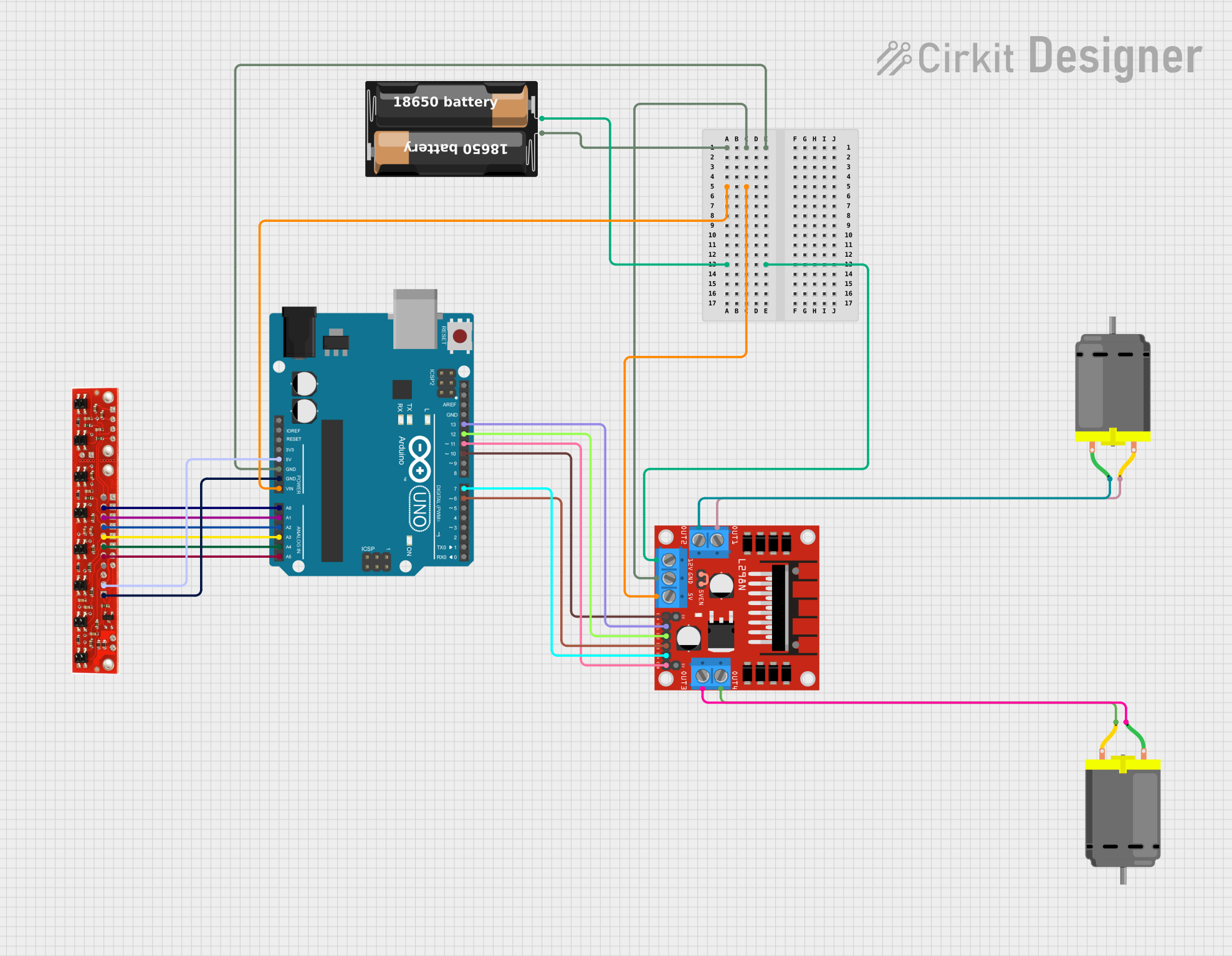
This circuit is designed to control two DC motors using an L298N DC motor driver, interfaced with an Arduino UNO microcontroller. The circuit also includes a line sensor for detecting lines or edges and a battery case to provide power to the system. The Arduino UNO is programmed to interact with the line sensor and control the motor driver, which in turn controls the speed and direction of the DC motors.
Component List
DC Motor
- Description: A standard DC motor used for converting electrical energy into mechanical motion.
- Pins: pin 1, pin 2
L298N DC Motor Driver
- Description: A motor driver module capable of driving two DC motors or one stepper motor.
- Pins: OUT1, OUT2, 12V, GND, 5V, OUT3, OUT4, 5V-ENA-JMP-I, 5V-ENA-JMP-O, +5V-J1, +5V-J2, ENA, IN1, IN2, IN3, IN4, ENB
Line Sensor
- Description: A sensor module used to detect lines or edges, commonly used in robotics for path following.
- Pins: 8, 7, 6, 5, 4, 3, 2, 1, +5v, GND
My Battery Case
- Description: A case that holds batteries to provide power to the circuit.
- Pins: +, -
Arduino UNO
- Description: A microcontroller board based on the ATmega328P, widely used for building digital devices and interactive objects.
- Pins: UNUSED, IOREF, Reset, 3.3V, 5V, GND, Vin, A0, A1, A2, A3, A4, A5, SCL, SDA, AREF, D13, D12, D11, D10, D9, D8, D7, D6, D5, D4, D3, D2, D1, D0
Wiring Details
DC Motor 1
- pin 1 connected to L298N DC motor driver OUT3
- pin 2 connected to L298N DC motor driver OUT4
DC Motor 2
- pin 1 connected to L298N DC motor driver OUT2
- pin 2 connected to L298N DC motor driver OUT1
L298N DC Motor Driver
- OUT1, OUT2, OUT3, OUT4 connected to respective DC Motor pins
- 12V connected to My Battery Case +
- GND connected to My Battery Case - and Arduino UNO GND
- 5V connected to Arduino UNO Vin
- 5V-ENA-JMP-I connected to 5V-ENA-JMP-O (jumper setting for enabling 5V)
- ENA connected to Arduino UNO D10
- IN1 connected to Arduino UNO D13
- IN2 connected to Arduino UNO D12
- IN3 connected to Arduino UNO D6
- IN4 connected to Arduino UNO D7
- ENB connected to Arduino UNO D11
Line Sensor
- +5v connected to Arduino UNO 5V
- GND connected to Arduino UNO GND
- Pins 7, 6, 5, 4, 3, 2 connected to Arduino UNO A0, A1, A2, A3, A4, A5 respectively
My Battery Case
- connected to L298N DC motor driver 12V
- connected to L298N DC motor driver GND and Arduino UNO GND
Arduino UNO
- GND connected to L298N DC motor driver GND and Line Sensor GND
- Vin connected to L298N DC motor driver 5V
- 5V connected to Line Sensor +5v
- A0-A5 connected to Line Sensor pins 7-2 respectively
- D10 connected to L298N DC motor driver ENA
- D11 connected to L298N DC motor driver ENB
- D13 connected to L298N DC motor driver IN1
- D12 connected to L298N DC motor driver IN2
- D6 connected to L298N DC motor driver IN3
- D7 connected to L298N DC motor driver IN4
Documented Code
Arduino UNO Code (sketch.ino)
void setup() {
  // put your setup code here, to run once:

}

void loop() {
  // put your main code here, to run repeatedly:

}
Note: The provided code is a template and does not contain any functional code to control the motors or read from the line sensor. This will need to be implemented according to the specific requirements of the application.