
Arduino UNO Based Temperature Monitoring System with LCD Display and Fan Control
View and Edit Project In Cirkit Designer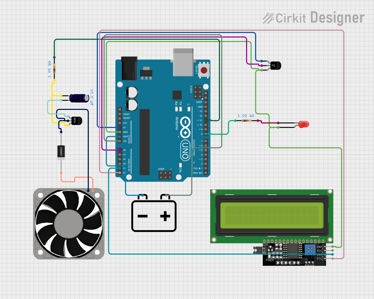
Circuit Documentation
Summary
This circuit is designed to interface an Arduino UNO with a temperature sensor (LM35), an LED, an LCD display, a 12V battery, a rectifier diode, an electrolytic capacitor, resistors, an NPN transistor, and a 12V fan. The Arduino UNO is used as the central processing unit, reading temperature data from the LM35 sensor and controlling the LED and fan based on certain conditions. The LCD display is used to show relevant information to the user. The circuit is powered by a 12V battery, which is regulated for the Arduino and other components.
Component List
- Arduino UNO: A microcontroller board based on the ATmega328P. It has digital input/output pins, analog inputs, a USB connection for programming, and power management features.
- LED (Red, Two Pin): A simple light-emitting diode that emits red light when powered.
- 12V Battery: Provides the power source for the circuit.
- 1N4007 Rectifier Diode: A diode that allows current to flow in only one direction, used for protecting components from reverse voltage.
- Electrolytic Capacitor: A capacitor with a capacitance of 0.00001 Farads, used for filtering and power smoothing.
- Temperature Sensor (LM35): An analog temperature sensor that provides a voltage output proportional to the temperature.
- Resistors: Two resistors with a resistance of 1000 Ohms, used for current limiting and voltage division.
- NPN Transistor: A bipolar junction transistor used for switching and amplification.
- 40mm Fan (12V): A cooling fan that operates at 12V.
- LCD Display 16x4 I2C: A liquid crystal display with an I2C interface for displaying text and numbers.
Wiring Details
Arduino UNO
- 5V to Temperature Sensor (LM35) +Vs
- GND to Temperature Sensor (LM35) GND, LED anode, LCD Display GND, and 12V Battery -
- Vin to 12V Battery +
- A0 to Temperature Sensor (LM35) Vout
- A4 (SDA) to LCD Display SDA
- A5 (SCL) to LCD Display SCL
- D11 to Resistor (pin2)
- D8 to Resistor (pin1)
LED (Red, Two Pin)
- Anode to Arduino UNO GND
- Cathode to Resistor (pin2)
12V Battery
- + to Arduino UNO Vin
- - to Arduino UNO GND
1N4007 Rectifier Diode
- Cathode to 40mm Fan +12V
- Anode to NPN Transistor C and 40mm Fan -12V
Electrolytic Capacitor
- - to Resistor (pin1) and NPN Transistor B
- + to NPN Transistor E
Temperature Sensor (LM35)
- +Vs to Arduino UNO 5V
- Vout to Arduino UNO A0
- GND to Arduino UNO GND
Resistors
- Resistor 1: pin1 to Arduino UNO D11, pin2 to LED cathode
- Resistor 2: pin1 to Arduino UNO D8, pin2 to Electrolytic Capacitor -
NPN Transistor
- E to Electrolytic Capacitor +
- C to 1N4007 Rectifier Diode Anode and 40mm Fan -12V
- B to Electrolytic Capacitor -
40mm Fan (12V)
- +12V to 1N4007 Rectifier Diode Cathode
- -12V to 1N4007 Rectifier Diode Anode and NPN Transistor C
LCD Display 16x4 I2C
- SCL to Arduino UNO A5
- SDA to Arduino UNO A4
- VCC (Not connected in the net list, assumed to be connected to a power source)
- GND to Arduino UNO GND
Documented Code
Arduino UNO Code (sketch.ino)
void setup() {
  // put your setup code here, to run once:

}

void loop() {
  // put your main code here, to run repeatedly:

}
Note: The provided code is a template and does not contain any functional code. It needs to be populated with instructions to read the temperature sensor, control the LED and fan, and update the LCD display.