
Arduino Uno Smart Feeder with GSM Alerts and Ultrasonic Level Detection
View and Edit Project In Cirkit Designer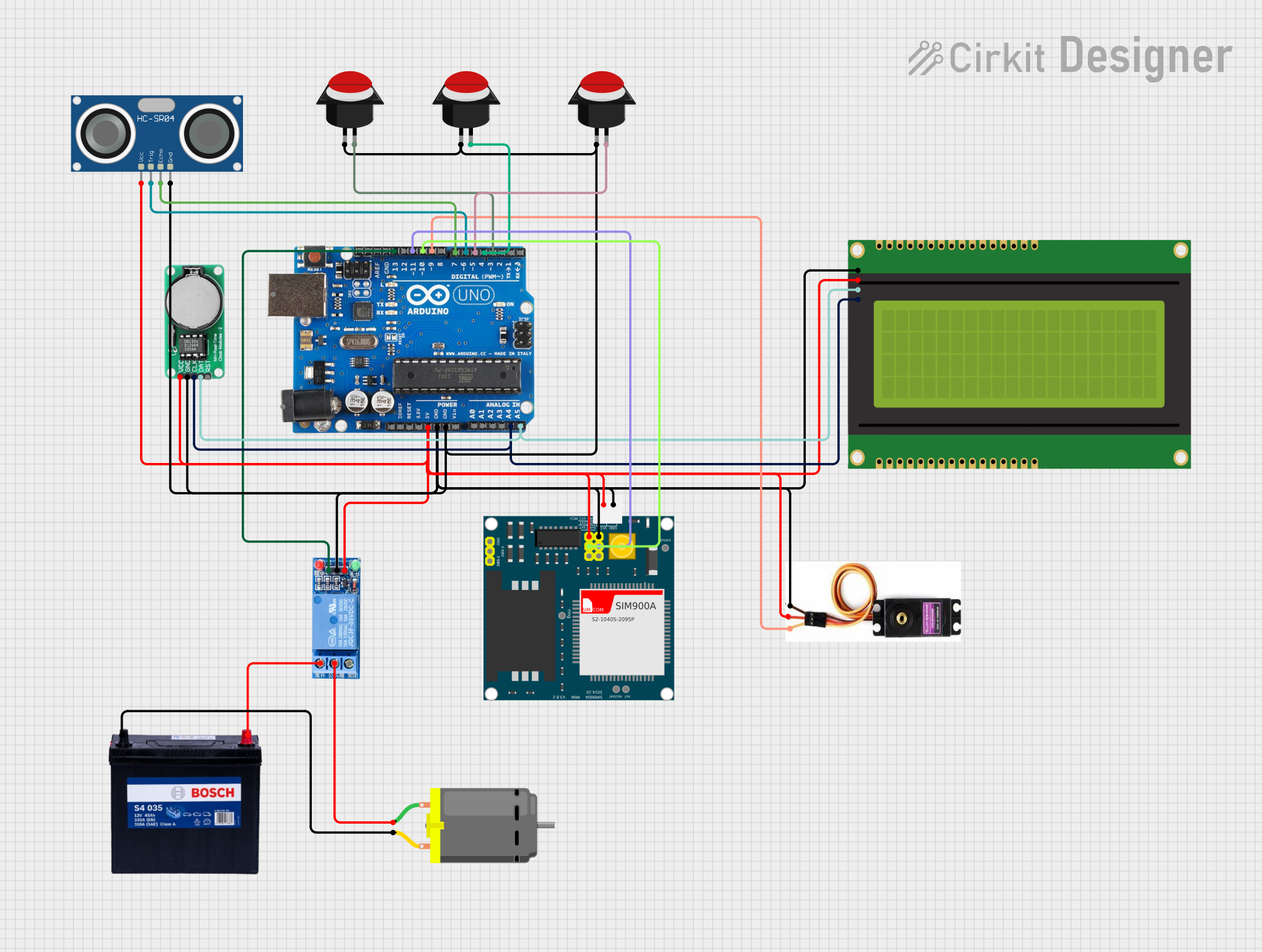
Circuit Documentation
Summary
This circuit is designed to control a servo motor, relay, and various sensors using an Arduino Uno R3. It includes an LCD display for user interaction, a real-time clock (RTC) for timekeeping, and a GSM module for sending SMS notifications. The circuit also features push buttons for setting the time and an ultrasonic sensor for distance measurement.
Component List
Arduino Uno R3
- Description: A microcontroller board based on the ATmega328P.
- Pins: D8, D9, D10, D11, D12, D13, GND, AREF, SDA, SCL, D0/RX, D1/Tx, D2, D3, D4, D5, 6, D7, A5/SCL, A4/SDA, A3, A2, A1, A0, Vin, 5V, 3.3V, RESET, IOREF, NONE, USB Jack, Power Jack
1 Channel Relay 5V
- Description: A relay module that allows control of high voltage devices.
- Pins: VCC, GND, IN, NC, COM, NO
SIM900A
- Description: A GSM module for sending and receiving SMS.
- Pins: GND, DB9-3 (RXD), DB9-2 (TXD), 5V, 3VR, 5VR, 3VT, 5VT, VCC, Ring, RESTART, RESET, STATUS
Servo Motor
- Description: A motor that can be controlled to move to a specific position.
- Pins: PWM, GND, VCC
20x4 I2C LCD Panel
- Description: An LCD display with I2C interface.
- Pins: GND, VCC, SDA, SCL
DS1302 RTC
- Description: A real-time clock module for timekeeping.
- Pins: VCC, GND, CLK, DATA, RST
Push Button Round
- Description: A simple push button for user input.
- Pins: leg0, leg1
HC-SR04 Ultrasonic Sensor
- Description: A sensor for measuring distance using ultrasonic waves.
- Pins: VCC, TRIG, ECHO, GND
DC Motor
- Description: A motor that runs on direct current.
- Pins: pin 1, pin 2
12V 200Ah Battery
- Description: A high-capacity battery for powering the circuit.
- Pins: GND, 12V
Wiring Details
Arduino Uno R3
- D9: Connected to PWM of Servo Motor
- D10: Connected to 5VT of SIM900A
- D11: Connected to 5VR of SIM900A
- D13: Connected to IN of 1 Channel Relay 5V
- D3: Connected to leg1 of Push Button Round
- D4: Connected to leg1 of Push Button Round
- D5: Connected to leg1 of Push Button Round
- 6: Connected to TRIG of HC-SR04 Ultrasonic Sensor
- D7: Connected to ECHO of HC-SR04 Ultrasonic Sensor
- A5/SCL: Connected to SDA of 20x4 I2C LCD Panel and DATA of DS1302 RTC
- A4/SDA: Connected to SCL of 20x4 I2C LCD Panel and CLK of DS1302 RTC
- GND: Connected to leg0 of Push Button Round, GND of HC-SR04 Ultrasonic Sensor, leg0 of Push Button Round, GND of 20x4 I2C LCD Panel, GND of 1 Channel Relay 5V, GND of SIM900A, GND of Servo Motor, GND of DS1302 RTC
- 5V: Connected to VCC of 20x4 I2C LCD Panel, VCC of 1 Channel Relay 5V, VCC of SIM900A, 5V of SIM900A, VCC of HC-SR04 Ultrasonic Sensor, VCC of Servo Motor, VCC of DS1302 RTC
1 Channel Relay 5V
- NC: Connected to 12V of 12V 200Ah Battery
- COM: Connected to pin 1 of DC Motor
- GND: Connected to GND of Arduino Uno R3
- VCC: Connected to 5V of Arduino Uno R3
- IN: Connected to D13 of Arduino Uno R3
SIM900A
- 5VT: Connected to D10 of Arduino Uno R3
- 5VR: Connected to D11 of Arduino Uno R3
- GND: Connected to GND of Arduino Uno R3
- VCC: Connected to 5V of Arduino Uno R3
- 5V: Connected to 5V of Arduino Uno R3
Servo Motor
- PWM: Connected to D9 of Arduino Uno R3
- GND: Connected to GND of Arduino Uno R3
- VCC: Connected to 5V of Arduino Uno R3
20x4 I2C LCD Panel
- SDA: Connected to A5/SCL of Arduino Uno R3
- SCL: Connected to A4/SDA of Arduino Uno R3
- GND: Connected to GND of Arduino Uno R3
- VCC: Connected to 5V of Arduino Uno R3
DS1302 RTC
- DATA: Connected to A5/SCL of Arduino Uno R3
- CLK: Connected to A4/SDA of Arduino Uno R3
- GND: Connected to GND of Arduino Uno R3
- VCC: Connected to 5V of Arduino Uno R3
Push Button Round
- leg1: Connected to D3, D4, D5 of Arduino Uno R3
- leg0: Connected to GND of Arduino Uno R3
HC-SR04 Ultrasonic Sensor
- TRIG: Connected to 6 of Arduino Uno R3
- ECHO: Connected to D7 of Arduino Uno R3
- GND: Connected to GND of Arduino Uno R3
- VCC: Connected to 5V of Arduino Uno R3
DC Motor
- pin 1: Connected to COM of 1 Channel Relay 5V
- pin 2: Connected to GND of 12V 200Ah Battery
12V 200Ah Battery
- 12V: Connected to NC of 1 Channel Relay 5V
- GND: Connected to pin 2 of DC Motor
Documented Code
#include <LiquidCrystal_I2C.h>
#include <Wire.h>
#include <RTClib.h>
#include <Servo.h>
#include <SoftwareSerial.h>

// Initialize LCD, RTC, Servo, and GSM
LiquidCrystal_I2C lcd(0x27, 16, 4);  // Adjust the I2C address if necessary
RTC_DS3231 rtc;
Servo servoMotor;
SoftwareSerial sim900(11, 10);  // GSM SIM900A RX to 11, TX to 10

// Pin definitions
const int relayPin = 13;
const int servoPin = 9;
const int hourButton = 3;                    // Button to increment hour
const int minuteButton = 4;                  // Button to increment minute
const int confirmButton = 5;                 // Button to confirm time
const int triggerPin = 6;                    // Ultrasonic trigger pin
const int echoPin = 7;                       // Ultrasonic echo pin
const float distanceThreshold = 45.0;       // Distance threshold in cm
const char phoneNumber[] = "+639686791256";  // Replace with target phone number
const char phoneNumbers[] = "+639550468037";  // Replace with the second target phone number

boolean timeSet = false;   // Flag to indicate if the time has been set
int hour = 1, minute = 0;  // Default time settings

// Timing variables
unsigned long previousMillis = 0;
const